We thought we’d take a break from the brains and take a look at the brawn — the differential. The diff is perhaps the most crucial component in getting the power to the ground and performs three main tasks: it distributes torque from the tailshaft to the driving wheels; allows the inner and outer wheels to rotate at different speeds during turns; and maintains equalised driving force between both driving wheels under all conditions.
The diff is a tricky bit of gear and comes in a variety of designs and sizes, but when it comes to getting serious torque to the wheels of your street machine, the Ford nine-inch (and its derivatives) is by far the most popular choice.
The name nine-inch comes from the diameter of the crown wheel, or ring gear and there are other terms you’ll hear too, such as single-wheeler, limited slip, mini-spool and full-spool.
There are also variations on the basic diff, like Detroit Locker and Truetrac, and even a new performance unit invented in Geelong.

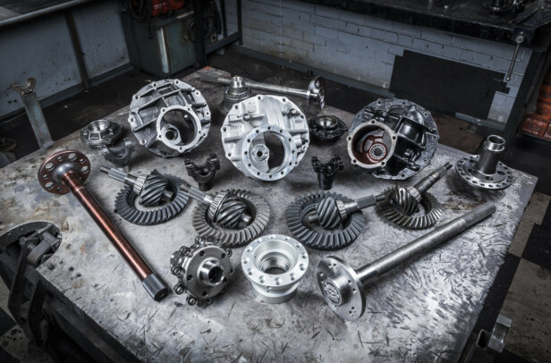
The main photo (top of page) shows an exploded view of a nine-inch limited slip diff that Supa-Trik Engineering in Dandenong allowed us to dismantle. You can see that the inner end of each axle has splines that fit into the centre of a gear with teeth on one side. These are called side gears and they mesh with the assembly of four smaller pinion gears shown between them.
The ends of the shafts on which the pinion gears are mounted fit into corresponding holes in the cast iron differential case. These are normally obscured so we cut a quadrant piece out of the ring gear to let you see two of them.
As the large drive pinion at lower left turns in a clockwise direction, it drives the ring gear around in a clockwise direction. Because the differential pinion-gear mounting shafts are fixed in the holes in the case when the unit is assembled, they rotate (end over end) along with the ring gear and case.
So as the pinion gears rotate, driven by the mounting shafts in the diff case, they drive the side gears which transmit drive through the axles to the wheels (photo 2, bottom of page).

DEGREES OF FREEDOM
Now let’s say you’re doing a full-lock turn in your car. The inside wheel rotates much slower than the outside wheel and that’s allowed by the pinion gear assembly.
Besides rotating end over end, the pinion gears are also free to turn in either direction on their shafts as indicated by the green arrow in photo So during our full-lock turn, the outside (including its axle and side-gear) is forced to turn faster than the opposite one, and to compensate the pinion gears simply turn on their shafts. Even as they do this, they continue to rotate with the differential case and ring-gear assembly as a whole, applying driving torque to both wheels.
To simplify how the pinion gears work with the side-gears, let’s forget about most of the teeth and think in terms of levers. In photos 4 and 5 we’ve painted the gears to assist with this idea. In our example, the lower side gear drives the inside wheel and because it is rotating much slower while we turn, it acts as a fulcrum, or pivot point.
So as the pinion gears are pulled around by their shafts, they turn the other side gear further than the distance covered by the pinions. And because drive is through the centre of the figurative lever (pinion gear) and the ends of the lever (engaged teeth) are always at equal distances from the centre, equal torque is always applied to both side-gears.
This brings us to the fundamental problem with open or single-wheeler differentials. When one wheel loses traction it becomes much easier to drive than the one that still has grip, so the wheel with the grip creates a fulcrum and the ‘lever’ effect causes the wheel without grip to spin without driving the car.
Traction requires friction and since that can’t be applied between the tyre and the road, the solution is to create friction within the differential itself. This concept became the all-popular limited slip differential.

FRICTIONAL RELATIONSHIP
In the Ford nine-inch limited slip diff (LSD), internal friction is created in a clutch pack (see photo 5, bottom of page) similar to those found in automatic transmissions. The friction plates are splined onto the clutch hub while the intermediate steels have semi-circular protrusions, or ears, that engage semi-circular cut-outs in the differential cover.
Because the clutch hub is splined onto the left (from the rear of the car) axle, and the cover forms part of the case containing the pinion gears, friction between the plates in the clutch-pack ends up acting between the left axle and the differential case. Whenever the left axle turns faster than the case and attached pinion shafts (during right turns) or slower (during left turns), friction in the clutch pack limits the amount of slip that can occur.
The block in which the pinion gear shafts are located has a hole in each corner on the side facing the clutches. The four springs in these holes (one is partially removed in the shot) apply pressure to the folded steel thrust plate shown in photo 7, bottom of page. This plate, in turn, applies pressure to the left side gear, which bears against the clutch hub and applies preload to the plates. Also, the curvature of the contact faces on the teeth of the pinions and side gears tends to push the whole assembly apart.
This pushes the side gears out towards the wheels and applies a good deal of pressure to the clutch-pack. During a hard launch this pressure can become so great that a standard cast iron cover can have the middle broken out of it (photo 8, bottom of page). Supa-Trik supplies the billet steel replacement cover shown in photo 6, which is strong enough to resist these forces.

LOCK STOCK
Another way of avoiding slippage between the driving wheels is to simply lock both axles together. A mini-spool is the easiest and least expensive way of doing this. There are two types available and both
are shown in photo 9. To fit one, the pinion gears, side gears and retaining block for the pinion gear shafts are removed from the case and a mini-spool is inserted in place of them. Then, the original pinion gear shafts are re-inserted locking the mini-spool to the case. The splines on the axles fit directly into internal splines in the spool thus locking the axles together.
Some American nine-inch diffs (and the odd Australian unit) have only two pinion gears from the factory. If you have one of these units you’d use the mini-spool with just two holes. If you have the heavier duty unit with four pinion gears, then the spool with four holes is the one you’ll need. Mini-spools don’t cost very much so trying to make your own by welding up your pinion gears is a great deal of pointless work.
In terms of permanently locked axles, the next step up the strength tree is the full-spool. These come in steel or aluminium and replace everything between the axles. Both types are shown in photo 10 and you can see that the ring gear bolts directly onto them. These are very strong and are great for drag racing but not for going around corners.
If you do want to drive on the street, but want a fairly stout diff for off-street drags, there is a compromise. Photo 12 shows a Truetrac® diff (left) while the unit on the right is a Detroit Locker®.
Photograph 11 shows the locker installed in an aluminium case from Moser.
These units can take a bit of getting used to because of the suddenness of their action. However, they do lock up extremely well and handle major power while maintaining acceptable street behaviour. We’ll go into more detail about locker differentials next time around.
IN DETAIL:

- 1. An exploded view of a nine-inch LSD.

2. The large arrow shows how the shafts and pinion gears are driven by the differential case. The other arrow shows how the side-gears are carried with them. The axles fit into the internal splines in the side-gears.

3. As the green arrow indicates, the pinions are free to turn on their shafts as the whole assembly rotates with the differential case.


4. It’s easiest to grasp if you forget about most of the teeth and think in terms of levers. If the lower side-gear is held in place and then the pinion shaft is pulled over to the right, the other side gear will move twice as far as the pinion shaft.

5. In the Ford nine-inch LSD, internal friction is created in a clutch pack similar to those found in automatic transmissions. The friction plates are splined onto the clutch hub while the intermediate steels have semi-circular protrusions, or ears, that engage semi-circular cut-outs in the differential cover.

6. The springs apply preload to the side gear and clutch pack.

7. Too many hard launches will break a factory cast-iron cover. Still, it provides a look at the assembled
clutch pack in place.

8. These are mini-spools. Two pinion units are mounted on the one shaft so you’d use the mini-spool on the right. A heavy-duty diff has four pinions and uses the unit on the left. Welding up the gears (centre) is not recommended.

9. Whether they’re steel or aluminium, full-spools are about as tough as it gets. However, they can’t really be described as diffs because they don’t allow any independent rotation of the driving wheels. Drag cars, and some other racecars use them but they’re not much good on the street.

10. A Detroit Locker installed in a neat aluminium Moser case.

11. A Truetrac diff on the left and a Detroit Locker on the right. These are what you’d use if you want to drive your drag weapon on the street.
Comments