Without an effective lubrication system, your engine would quickly seize solid — even the most mechanically inept person understands this simple concept. However, apart from reducing friction, oil performs a multitude of other tasks in an internal combustion engine. It keeps components cool as well as carrying contaminants out of the engine, trapping them in the filter. These are extremely important tasks.
Less well known, however, is that oil plays a part in neutralizing the reactive by-products of combustion, that it absorbs certain vibrations, and that it transmits forces between the components that it separates. In more modern engines it’s also used for hydraulic actuation of things like variable lift camshafts. In short, oil is important stuff but it can’t do its job unless it’s channelled to where it’s needed by a well designed distribution system, which is the subject of this article.
First published in the July 2006 issue of Street Machine
Oil Storage
The sump is probably the place to start. This is the container bolted to the bottom of an engine that stores the bulk of your engine’s oil. It contains much more oil than is needed to fill the spaces between the bearings and other components, for a couple of reasons.
Firstly, the more oil there is circulating in an engine, the more heat it can absorb and carry back to the sump where it’s cooled by airflow under the car — this is one reason why performance sumps have enlarged reservoirs.
Secondly, oil wears out. As it circulates through an engine, the various properties necessary for it to fulfil the aforementioned roles diminish. Therefore, the greater the amount of oil in the engine, the longer it will last before it becomes worn out.

Deep Well
All sumps have a section built into them which concentrates the excess oil in a deep well. It’s from low in this area that the oil pump pick-up draws oil. This stops the pick-up from becoming uncovered during braking, acceleration and cornering, when the oil gets thrown around a fair bit. Exposing the pick-up means the pump sucks air. This is bad, as it results in an instantaneous drop in oil pressure, which can have catastrophic consequences.
You must be far more diligent regarding oil levels in modern engines, especially overhead-cam examples. With your old red six you may have been able to get away with waiting ’til the tappets started to clack before bothering to top up the oil. However, even the briefest period of zero or low oil pressure can destroy valvetrain systems on many modern engines.
Dry Argument
So far, we’ve been talking about wet sumps, in which the sump acts as an oil reservoir. However, very high performance engines are usually fitted with dry sump systems. Here, as you might guess from the name, the sump doesn’t store oil; it simply catches it and directs it to the inlets of an externally-mounted multi-stage scavenge pump that immediately removes it and sends it to a remotely mounted oil tank.

Under pressure
Vintage engines relied on a splash-fed oiling system. However, by the 1940s the vast majority of passenger car engines had switched to the modern pressure-fed oiling set-up. Such systems need a pump of some sort to force oil into the engine. The eccentric bi-rotor or gerotor (gear-rotor) type is the most common. It consists of two interlinked rotors that have different diameters and different numbers of lobes (see description, below).
In general terms, eccentric bi-rotor pumps are considered to be the most efficient because the volume of oil transferred during each revolution of the rotors is quite large and also because the inlet and outlet ports in the pump housing cover many degrees of rotation. Traditional distributor-driven pumps and newer crank-driven pumps both utilise eccentric bi-rotor designs.
Excessive pressure
Mechanical pumps struggle to maintain adequate pressure at low engine speeds. To ensure adequate pressure (and volume) throughout an engine’s operating speed, oil pumps are designed to supply much more pressure than required. Accordingly, they are fitted with spring-loaded pressure bypass valves that open when the pressure becomes too high.
High pressure oil pumps have stronger springs but it’s important to realise that oil pressure doesn’t act directly in keeping engine components separated from each other. This is logical when you think about it: how could a pump pressure of even 100psi play any role in separating a conrod and crankpin that are being forced together by thousands of pounds of pressure during the combustion stroke?
Aftermarket high-pressure and high-volume pumps simply ensure that an adequate volume of oil is forced into all the necessary sections within your engine.

How much?
In terms of how much pressure is needed, the old adage 10psi for every thousand revs isn’t a bad rule of thumb but it’s not universally applicable. For instance, in an engine that turns to 7000rpm, the pump might make 70psi by 3000rpm and then stay steady until redline. Keeping the pressure as low as possible reduces power loss and when using synthetic oil, pressure can be lower than the golden rule. Nizpro says it builds V8s with as little as 40psi, whereas the company’s 1200hp BA turbo six uses around 70psi. While keeping the bearings cool is always important, it’s absolutely vital in an engine like that.
This brings up clearances. Looser fits will pass more oil and therefore need a larger volume of oil. So while more revs calls for more pressure, so does more power. The exact figure for your application will depend on your engine builder’s preferences gained by experience — discuss it.

Filter
From the pump, oil passes into the oil filter. For most engines this is likely to be a treated paper element, spin-on canister type. Oil enters the outer ring of holes and is forced through the outside of the paper concertina into the centre and then out into the engine through the threaded hole in the centre of the mounting plate. Most often, such filters are mounted directly to the block but they can also be fitted to remotely mounted adaptors.
What’s the drill?
After emerging from the filter, oil must be able to get where it’s needed. This is accomplished by drilling long holes, called oil galleries (read more, below), into the structure of the block, as well as into separate components so that they intersect with the galleries. While the basic premise is the same, engine manufacturers each go about this in a slightly different manner and factory systems are often modified in high performance applications.
Basically, the main bearings should receive oil before any other components. Because the rod journals are lubricated by galleries drilled through the crank from the main journals, giving the mains oiling priority also takes care of the big-ends early in the lubrication cycle. After this, the cam bearings can receive oil. However, if they’re fed by drillings from the main bearings, screw-in restrictor plugs may be needed to prevent too much oil being diverted from the mains and rods.
To feed the top-end, oil is forced into the lifter bores from where it’s forced through drillings in the lifters, up the hollow pushrods, through the heel of the rocker and into the valve covers.
Drain Back

After reaching the rocker gear in the heads, oil returns to the valley area via the clearance around the holes in the head that the pushrods pass through. In some engines there are additional holes cast into the heads to assist with oil drain-back.
Back in the valley, long slots over the cam lobes allow returning oil to flow down onto the lobes before draining back towards the bottom of the engine. As the oil drips out of the cam tunnel and into the crankcase, the spinning crank and rods splash it all over the cylinder walls. This lubricates the walls to some extent but the main source of cylinder lubrication is oil thrown out of the side clearances between the big ends and crankshaft webs. Oil is scraped off the cylinder wall by the bottom ring (commonly called the oil control ring), and then flows back to the sump to start the whole process again.
Conclusion
As we said at the beginning, oil has an extremely demanding role. And now that you’ve got a basic understanding of your engine’s lubrication system, we’ll take a look at upgrading your stock lubrication system for high-performance applications, as well as having a more detailed look at dry sump systems in part two, here.
Eccentric Bi-rotor Pumps


This type of pump uses an outer rotor (with internal lobes) that rotates within a housing. Inside this outer rotor is an offset-mounted inner rotor (with external lobes) which rotates via a drive mechanism. In many OE set-ups the inner rotor (the pump) is driven by a shaft connected to the end of the distributor shaft, or by a gear or chain driven directly off the front of the engine.
In an eccentric bi-rotor pump, the outer rotor always has one more lobe than the inner rotor. The differing number of lobes and the different diameter of the two rotors mean that there are always a number of spaces between the lobes of the two rotors. As the rotors turn, the spaces between them constantly grow and shrink. Inlet ports are positioned in the areas where the spaces are getting bigger, while the outlet ports are positioned in the areas where the spaces are getting smaller.
With all pumps of this type, pressure is determined by engine speed. The above diagrams track the progress of just one of these spaces through one revolution. Note how the inner and outer lobes change phase in relation to each other. The red dot starts out between lobes A and B. However, by the end of one revolution the outer rotor is now trailing the inner rotor, hence the blue dot is now between A and B. This action is continuous.
Oil Galleries

If you could somehow freeze the oil in your engine and lift it out, you’d see something like this. This configuration is commonly known as a priority system because it supplies oil to the main bearings first. Either the front or rear cross-drillings can be chosen for the pump inlet, while restrictor plugs (shown in blue) are fitted to the lifter galleries at the pump end, ensuring that the bulk of the oil goes to the long drilling that feeds the main bearings.
Although restrictors are shown fitted in both ends of each lifter gallery, this is just to indicate where they are placed. In service they are only fitted at the end which is being fed pressurised oil from the oil pump.

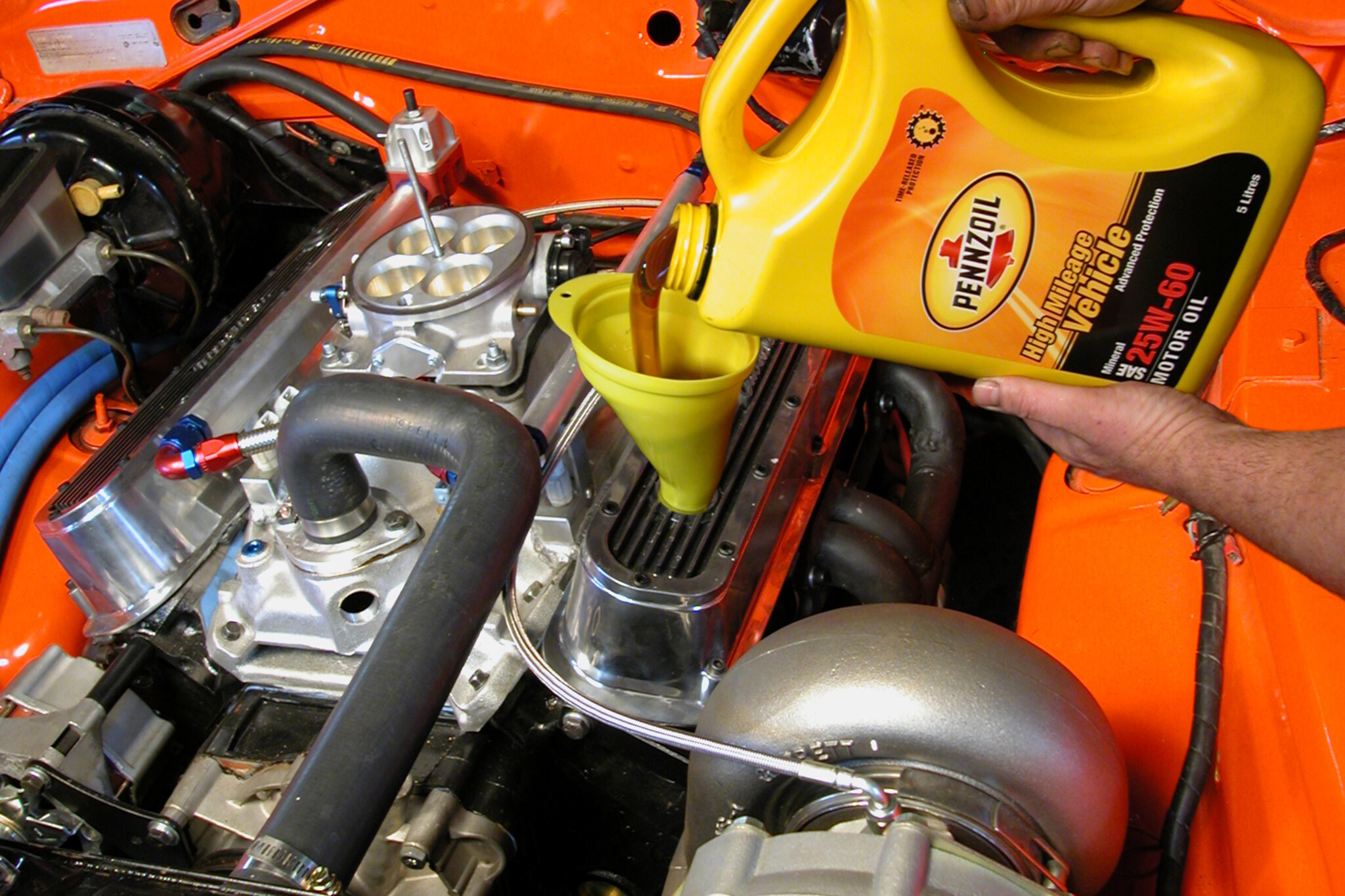
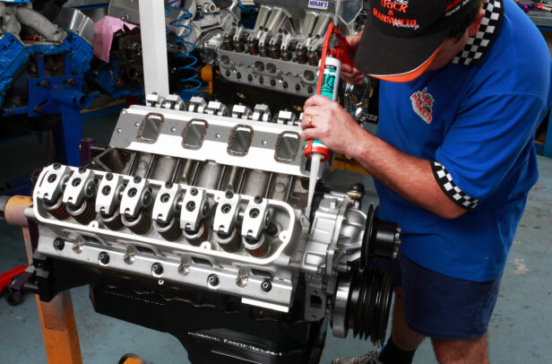
1. Like tyres and brake pads, oil is consumable and may need topping up between changes. A flashing oil light is not the sign to top up — it’s telling you there’s no oil pressure and irreparable damage is being done. Regularly check your oil level.

2. This is an upside-down view but you can clearly see how oil running out of the cam tunnel down into the crankcase is going to get splashed over the cylinder walls by the rotating crank and rods.

3. Crescent gear pumps are found mainly in automatic transmissions but as with eccentric bi-rotor pumps they have spaces that increase and decrease as the internally meshed gears rotate. The crescent traps oil between the teeth as they rotate from inlet to outlet.

4. At the top centre of the paper canister is a bypass valve which opens to bypass the filter element if it becomes clogged. A ring-shaped flap covers the circle of inlet holes and only allows flow in one direction. This keeps the filter full of oil when the engine is shut off.

5. To help oil flow into the filter, many engine builders enlarge and chamfer the filter entry port as Pav-Tek has done here.

6. This rendering of a Harrop V8 Supercar crankshaft shows the universal method of feeding pressurised oil into the big-end bearings via oil galleries (drilled holes) that run from the main bearings/journals through the crank webs and into the rod journals or big-end bearings.
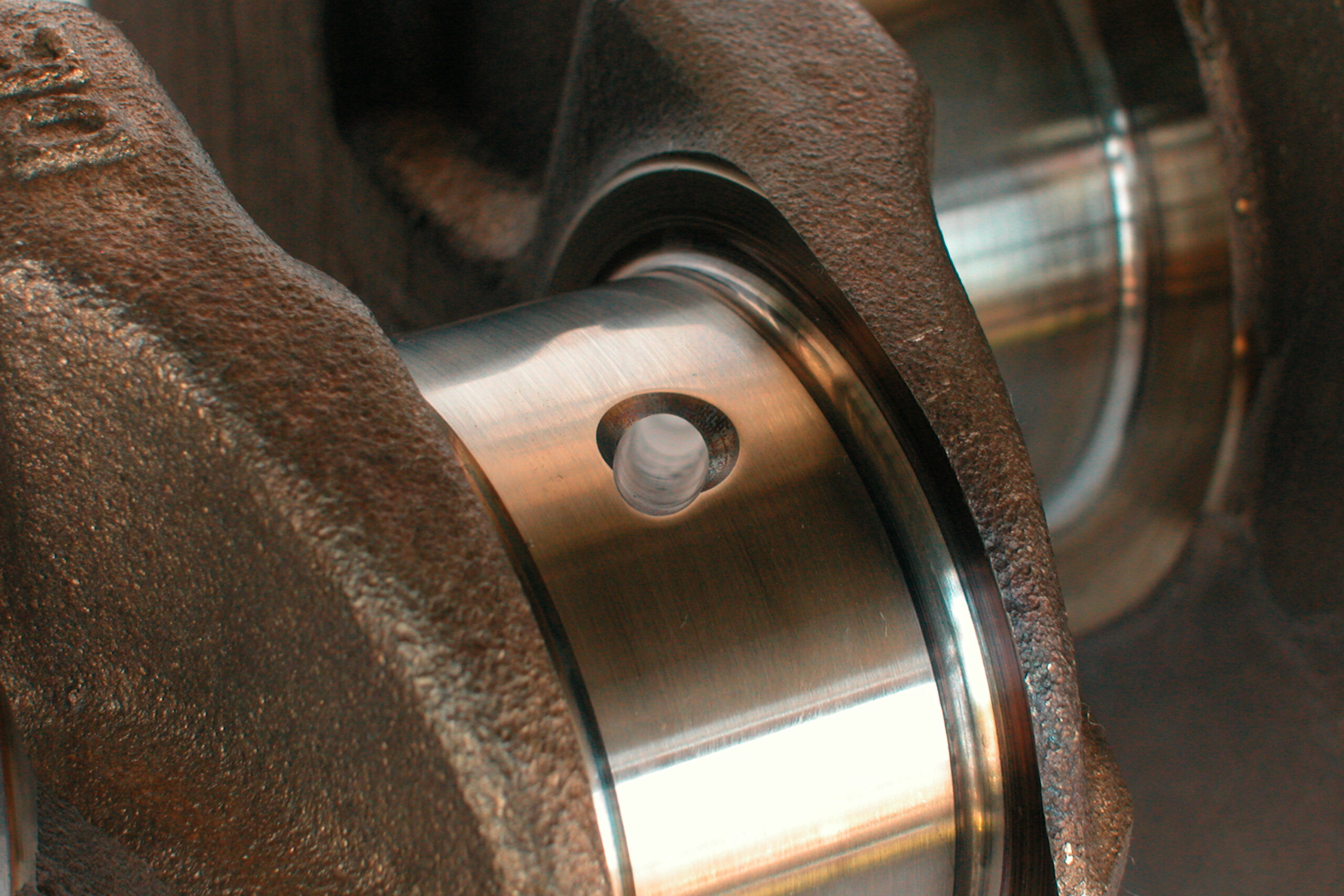
7. Here you can see how the oil gallery runs through a crank. Note the chamfer around the oil hole — this helps oil flow out of the hole and in between the bearing and journal surface as quickly as possible.

8. If you look carefully down the front face of this lifter bore you can see the opening through which oil passes into the body of the lifter.

9. With grooved main bearings like these, a continuous supply of pressurised oil is fed to the rod journals as long as the hole in the main journal of the crankshaft is positioned over the groove.

10. Note the small hole at the top of each main — this hole lines up with a hole in the bearing shell. The oil pump feeds pressurised oil through this gallery, which forms a protective fluid wedge between the stationary bearing and the rotating crank.
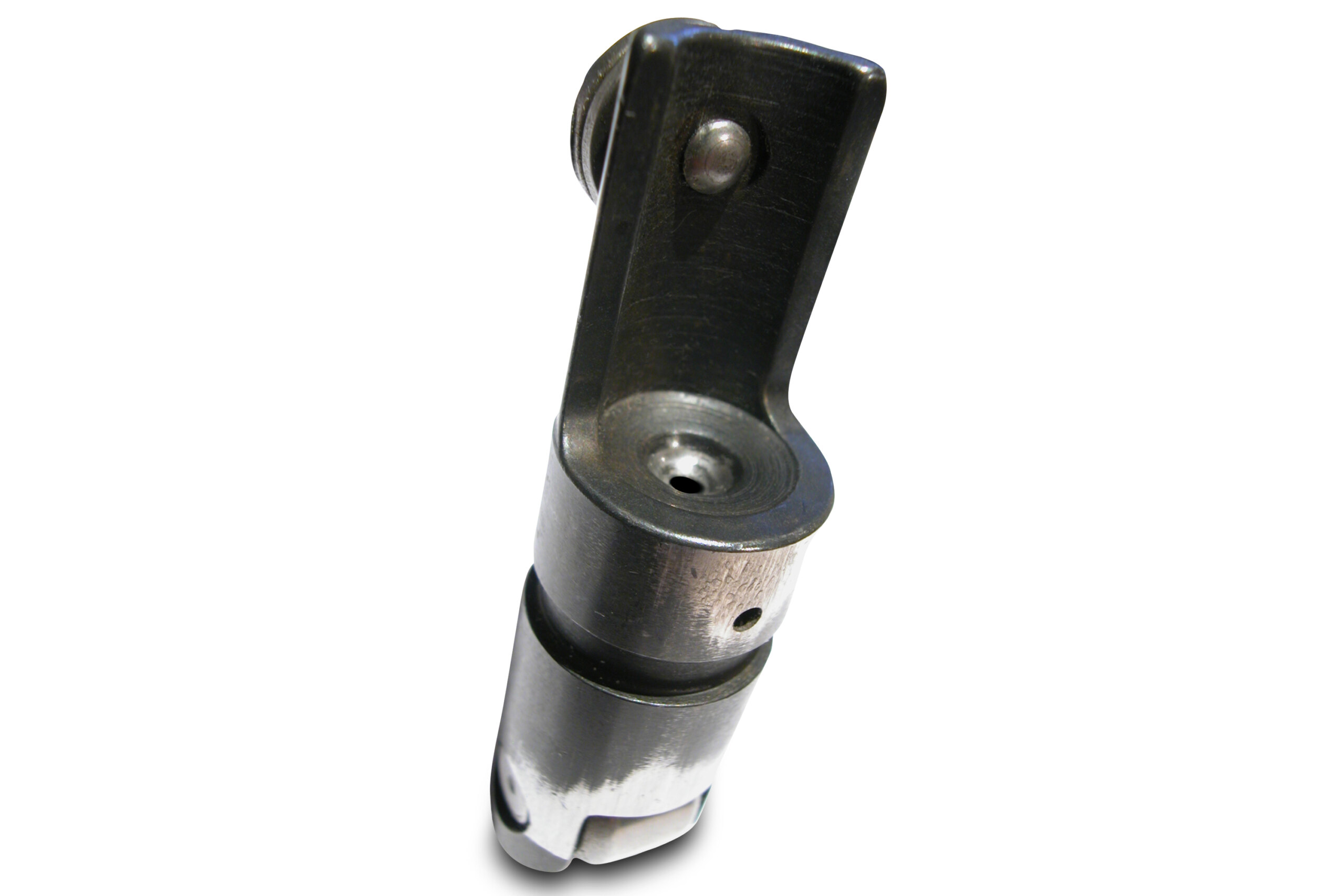
11. Looking at the top of the lifter, you’ll see a small cup which the pushrod sits in. In the middle of this cup is a small hole; this drilling runs down the lifter and intersects with another small hole drilled in its side. Oil is forced in through the side of the lifter, up through the top hole and into the pushrod.

12. Each cam in the BA Turbo head has its own gallery supplying oil to the lifters and (via drillings) to the cam journals. Compared to heads of yesteryear, it’s an intricate casting. The external cross-over between the galleries is visible at the bottom of the shot.

13. Oil is transferred from the lifter galleries to the rockers through the hollow pushrods. After draining from the heads back into the valley, oil flows through the long slots shown and onto the cam lobes.

14. Rockers have drillings in a number of different locations but they’re all fed from the tip of the pushrod. You can see the lubrication hole in this Yella Terra example. Some T&D Machine units incorporate an oil spray for cooling the springs.

15. Here’s what you don’t want to see when you remove your rocker covers and manifold. The black honey-like residue on everything indicates excessively long periods between oil changes.

16. The ventilation holes in this Cleveland sump are the result of a broken conrod. The guys from Betta Built engines tear down and rebuild 1200 old engines a month. They believe that almost 90 per cent of engine failures (even big blow-ups like this) can be traced back to oil contamination or oil starvation.

17. This is one method of oiling the small ends. These rods were prepared at Pav-Tek which uses the 10psi per 1000rpm rule. Its recommendation for oil and filter changes for a street car is every 5000km.
Comments