
In our previous feature we explained the what, where, why and how of your engine’s lubrication system — by now you should have a reasonable understanding of how it all works. This time around we’re going to take a closer look at how you can improve your engine’s oiling system for competition or performance applications.
First published in the August 2006 issue of Street Machine
PUMP IT UP
Each rotation of a mechanical pump moves a fixed volume of oil. All pumps are designed to supply a greater volume than required so that they achieve acceptable pressure at lowrevs. This creates excessive high-rev pressure (the pressure is determined by the system’s resistance to oil flow). Pressure is regulated via a spring-loaded valve within the pump that bleeds pressure into the sump when it opens. High-pressure pumps use a stiffer spring — greater pressure is thus required to open the bypass valve.
High-volume pumps, on the other hand, have larger internals that pump a greater volume of oil per
revolution. Factory Chev pumps are good examples: small-block versions contain gears with seven teeth, while big-block pumps (which can be fitted to small-blocks) have 12 teeth and pump a correspondingly larger volume of oil each revolution.
If a high-volume pump is fitted to an oil system that has the same volume and degree of restriction as when it was serviced by a standard volume pump, pressure will rise to maximum at lower revs and the bypass valve will be open for longer. The volume of oil passing through the oiling system may not increase much (at the same engine speed) because it’s governed by pressure, which is controlled by the spring in the bypass valve. At higher engine speeds, however, more oil will pass through the same system because the increased inertia of the oil in the crank drillings leading to the rod journals causes it to flow out through the rod clearances more rapidly.

PUMP UP THE VOLUME
Increasing the volume of the oiling system’s pressurised section — by adding things like remote filters or external coolers along with the lines leading to and from them — will often require the fitment of a high-volume pump or you run the risk of insufficient oil flow or pressure.
When adding additional oil lines, it’s important to remember that doubling the internal diameter of a
hose increases its internal volume (over the same length) by four. This can become significant in an
oiling set-up with a fair amount of external plumbing — especially prevalent in dry-sump systems.
Although the volume of the pressurised section in an oiling system has a great deal to do with overall
system pressure, the other contributing factor is the combined area of the outlets — from oiling holes in bearings, lifter bores, rockers, etc.
Increasing the size of any of these clearances or holes allows more oil to bleed off. A high-volume pump is useful for maintaining flow and pressure in engines with larger clearances.

BAFFLED
The instant any part of the oil pump pick-up is not submerged in oil, the pump will suck air and oil pressure will instantly drop. This instantaneous loss Of lubrication can cause equally immediate and catastrophic engine damage.
This can occur when inertia (expressed as G-force) during braking, acceleration or cornering, forces the oil in the sump to move away from the pick-up. To counteract such movement, all sumps have a low section built into them from which the pick-up draws oil. This is fine for production cars but in performance applications the oil can be thrown about with considerably increased force.
This means high-performance sumps contain a network of upright baffle plates as well as hinged gates designed to allow unimpeded oil-flow towards the pick-up while drastically restricting oil flow away from it.
SUPER SIZE ME
Increasing the volume of oil within the system has several benefits. As oil gets flung around by the rotating assembly or spurts from clearances it becomes aerated, diminishing its capacity to lubricate. Increasing revs increases pump flow yet the oil drains back into the sump at the same rate, which means less oil in the sump. Also, sump oil plays a significant part in engine cooling. All these issues can benefit from an increase in the volume of oil held in the sump.
In order to contain extra oil, performance sumps are widened rather than deepened as ground clearance is usually a concern. Often, only the low section around the pick-up is widened. In some applications the wider area extends the full length of the sump. Known as a kick-out, this design catches more of the oil that’s thrown off the rotating crankshaft.

OIL CONTROL
Drag created by oil flying about in the sump and crankcase can reduce power quite considerably so a
crank scraper can be a big help. A crank scraper is a plate mounted horizontally to the bottom of the block. The profile closely hugs the shape of the rotating crank and rod assembly. The narrow clearance between the two serves to skim off excess oil, preventing it from being thrown up into the crankcase.
The layout and size of oil galleries in production blocks are designed to operate over a wide rev-range which may not be ideal when used at sustained high-revs. For this reason, engine builders will block certain oil galleries, fit meshes, re-route oil galleries and insert restrictors to help control the flow of pressurised oil. Fitting roller rockers is a notable example as their design calls for less top-end lubrication. You can buy pushrods that restrict oil flow to the top-end, although the best option is to fit bronze sleeves with smaller oil transfer holes to the lifter bores.
It would take another article to explain all the different mods in any detail but such mods should really be left to the experts. For most hot streeters leaving a block standard works pretty well.

DRY ARGUMENT
All of these modifications work extremely well until you start operating near or above 1G, At this point the oil will sit up in the sump at up to a 45-degree angle. The legendary Smokey Yunik reckoned that at anything above 1.25G, the oil in a sump would be getting pretty close to vertical, rendering even the best baffle/trap-style wet sumps all but useless.
How much is 1G? Ross Hollingworth from MoTeC explains that a top-notch road car can experience about 0.8-0.9Gs under maximum braking or cornering, while a V8 Supercar can pull as much as 2.0G.
As drag cars approach the low eights they encounter similar problems due to acceleration and, like circuit cars, they need to start looking at dry sumps.
A dry sump differs in that the pan no longer stores the oil but simply serves a collector, with the oil reservoir mounted remotely. This means a dry sump can be much shallower, which allows the engine to be mounted lower, so the car can ride lower, which means it can go around corners even faster. Most traditional dry-sump pans are sheet metal but they can also be cast or carved from solid alloy billets. Depending on the engine these can serve as a stiffening member to bridge the void across the open crankcase.
Dry-sump systems feature externally mounted pumps that have one or two high-pressure outputs pumping oil into the engine, along with two, three or even four scavenging sections, called stages. These draw oil from the crankcase (reducing crankcase pressure), along with several other areas within the engine, and dump it back into the remote reservoir. Unlike wet sumps, which are flat and wide, dry-sump reservoirs are tall and skinny (usually with additional capacity) so they do not suffer the same oil slosh problems encountered by wet-sump systems.
Like internally mounted OE pumps, most dry-sump pumps operate at about half engine speed, although a range of different pulleys are available, enabling tuners to adjust the speed. As scavenged oil passes into the top of the reservoir tank, it flows across specially designed plates forcing it into thin layers — this allows trapped air bubbles to escape.
As an aid to separating oil and air, American company Dailey Engineering makes a centrifugal air/oil separator that fits inside its multi-stage pumps. It flings the heavier oil out against the inside of a housing — where it’s collected and sent to the oil tank — while air passes out through the centre. The company also makes pumps that attach directly to billet dry-sump extensions. Harrop Engineering manufactures a similar set-up for ultra-high performance LS1s. Not only are such installations compact, they eliminate plumbing between the sump and pump.
High-volume pumps can be bought from local manufacturers such as JP Performance and BDG
Engineering, while High Energy produces an extensive range of high-quality performance sumps for a wide variety of engines and applications.
A huge range of products and accessories including pick-ups, sumps, heavy-duty pumps and drive shafts, remote filters and mounting hardware can be sourced through companies such as VPW, Precision International, Rocket Industries, Superplus, Hardimans, American Autos, High Performance World, Sydney Competition Warehouse, Quantum Racing Industries, Sydney Speed Supplies or Superperformance. Give any of them a call and they’ll be only too happy to discuss your needs.
FOR ‘RON

Many consider an oil accumulator essential in high-performance applications. Basically it’s a cylinder containing a piston that’s plumbed into the pressurised section of the oiling system. When pressurised oil is forced into the accumulator, its piston is pushed up the cylinder compressing the air above it, creating a reservoir of pressurised oil. If oil pressure drops for any reason, this pressurised oil is forced into the engine to maintain pressure; it’s refilled when the oil pump restores system pressure.
A solenoid valve (green) traps oil when the engine is turned off. When the valve is released, the galleries are filled with pressurised oil immediately so there are not dry starts. Accumulators can be manually filled and pressurised so first starts with fresh engines can occur with full pressure and volume right from the first turn of the crank.
IN DETAIL:

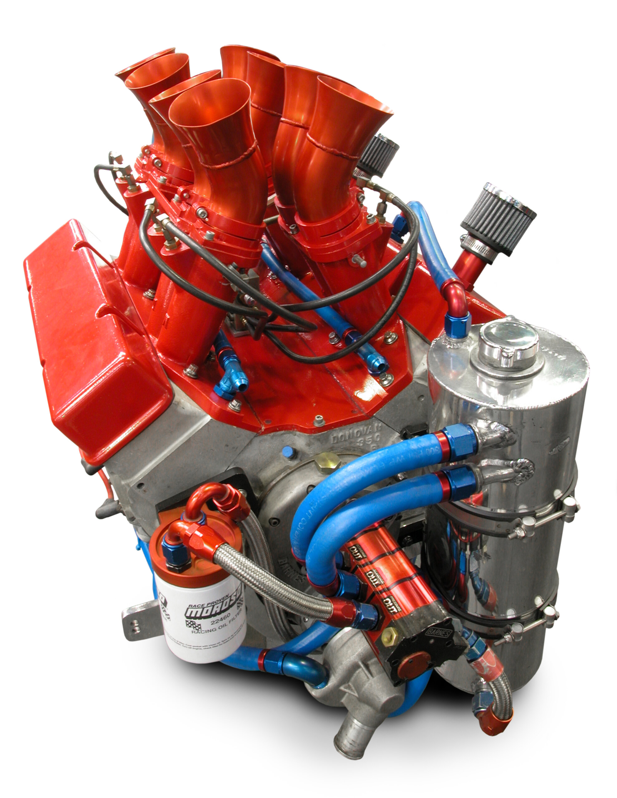
1. The front stage is the pressure section of the pump, drawing oil from the bottom of the reservoir and feeding it into the engine. The next two stages scavenge oil from the dry sump and pump it into the top of the reservoir

2. In a dry-sump system, not all scavenging is from the sump: this line connected to the suction side of the pump draws oil from the back of the valley, ensuring maximum scavenging under severe acceleration

3. Oil becomes less effective as it gets hotter so an oil cooler is mandatory on any circuit car. It’s not difficult to see how the cooler, filter and connecting lines increase the volume ofthe system

4. Engine bearings rely on oil pressure to prohibit metal-to-metal contact. A loss of pressure, for even the briefest time, can result in a catastrophic failure like this.

5. This LS1 sump was modified for performance and fitted to an LS7 swap into a Commodore. Custom work like this allows you to get exactly what you need. You can read the full story on the swap in Issue 18 of Street Machine Commodores.

6. A performance engine build-up should be accompanied by a performance pump. Different engines ave different requirements – high pressure, high volume or a pump with higher ratings for both. Any good speed shop should be able to advise you on which to go for.

7. Stock pump drives are never designed for high-rpm work. Always use an uprated pump drive when building a high-performance mill.

8. The insert for this heavily-modified LS1 sump ahows just how complex the system of baffles and one-way flaps can become in order to keep the pump pick-up immersed in oil during extreme braking, cornering or acceleration.

9. Harrop Engineering supplies this LS1 dry sump with an integral pump from local manufacturer BDG. This is an excellent low-profile system that tucks the pump right up out of harm’s way.

10. In this highly advanced BMW engine, if excessive G-force on the oil causes either of these solenoids (one each side) to be exposed, cam cover scavengers are actuated to maintain oil feed to the pump. This technology will eventually become commonplace.

11. Painted valleys, smoothed off castings and the drilling of extra holes all help the oil drain back into the sump as easily as possible.

12. The spinning crank and rods whip up quite an oil storm. The mesh in this High Energy Pro Circuit pan catches the mist and directs the oil to the bottom of the sump. The long grey strip at the top helps prevent oil being thrown up the side.

13. Note the tubing on the periphery of this rocker cover. Very small holes (jets) drilled into this plumbing is designed to spray oil directly onto the hot valve springs to help keep them cool.

14. Know as a gear pump, it’s what you’ll find inside virtually all dry-sump pumps. As oil enteres the inlet side, it’s trapped between the teeth of the gears and transported around the outside of the housing (not between the gears) to the outlet side where the slightly reduced volume forces it out under pressure.

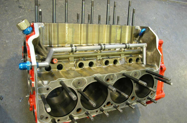
15. In some blocks, the configuration of the oil galleries is less than ideal for performance applications. The Cleveland (shown) is a notable example but other engines have problems and many different solutions involving supplementary external plumbing have been tried over the years.

16. Remotely mounted filters like this can be very effective. The worth of any filter is determined by its ability to trap the very smallest of particles yet not overly inhibit oil flow.

17. If the oil has to do extra things like cool turbocharger bearings, more of it will be needed. In such cases a high-volume pump is a good idea. Returns from turbochargers should enter the sump above the oil level, as in this Nizpro set-up.

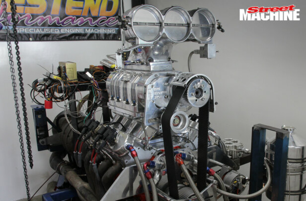
18. Externally mounted pumps like this Peterson unit at Competition Engines can be bracket-mounted and belt-driven (usually by a Gilmer belt) or, in certain track engines, mounted on the timing cover and directly driven by the cam.

19. Drillings like these into the piston’s bottom ring-land use oil scraped off the cylinder wall by the oil-control rings to supply additional lubrication to the gudgeon pin — normally most of this oil simply falls back to the bottom of the sump.

20. This is a BMW performance V8. Because the cams have to move more quickly than in standard
models, the oil pressure needs to be boosted before being fed into this front-mounted actuator.
Comments