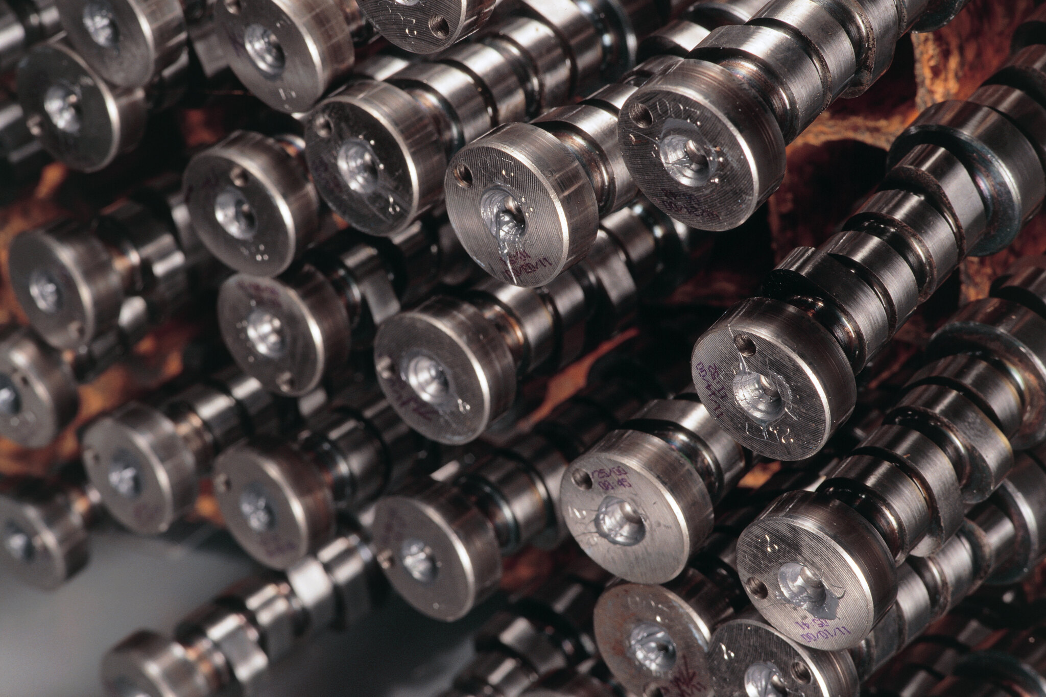
Even though it contains no moving parts, an engine’s camshaft is one if its most perplexing components. Ask the builder of any competitive race engine about their cam specifications and you’ll think you’ve just asked for the long, lost formula for turning lead into gold! Most professional engine builders would sooner sell their grandmother than reveal the details of their ‘special grind’. So what’s all the fuss about? After all they’re just sticks of steel with lots of lumps.
The answer lies in the shape of those lumps – known as lobes. Infinitesimally small changes in the profile and orientation of the lobes totally govern the operating characteristics, power spread and ultimate power output of your engine. The way a cam will perform within a particular engine combination is defined by a number of parameters, let’s look at what they are and the jargon used to describe them.
First published in the January 2004 issue of Street Machine
THE BASICS
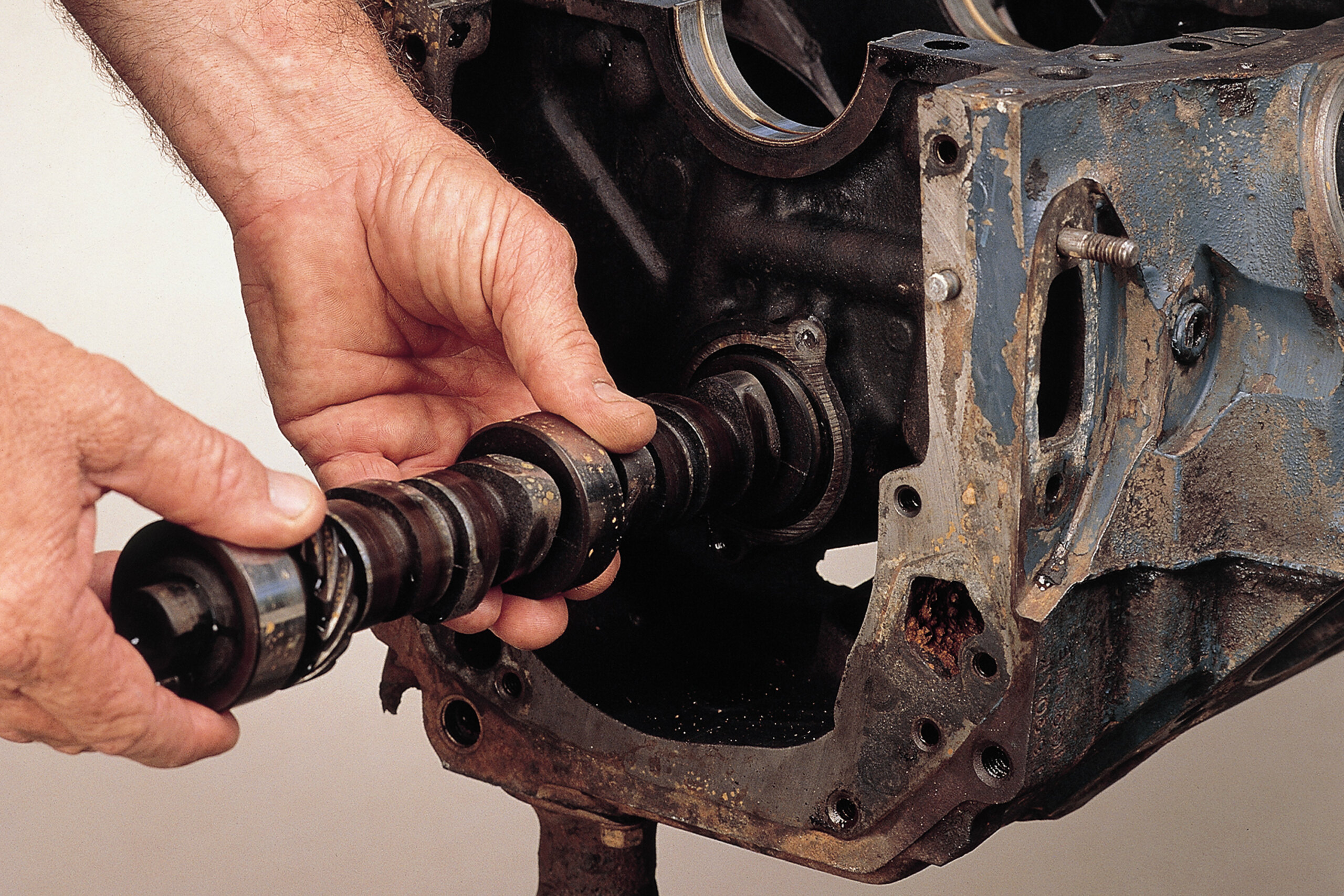
The cam is driven by the crankshaft and its job is to correctly time the opening and closing of the valves in relation to piston position. There are two basic types of cams; flat tappet and roller, which are then divided into solid and hydraulic – terms that describe the type of lifter used. Because the lifter type ultimately determines cam profile this terminology is the industry standard.
Flat tappet cams are found in older engines and some newer ones, while the better-performing roller cam is found in modern engines like the Gen III and new Falcon V8. Cam manufacturers offer roller cam conversions for older engines – understandably they’re a quite a bit more expensive than the flat tappet set-up due to all the extra components.
LIFT & DURATION
Cam lift is probably the most commonly quoted cam characteristic. It’s a measurement of how far a cam can lift a valve off its seat and is measured in thousandths of an inch. Aftermarket high ratio rockers increase valve lift but cam makers normally quote lift values (at the valve) using the standard rocker ratio.
Duration is the amount of time the camshaft holds the valves off their seats (open) and is measured in degrees of rotation. There are two methods of quoting duration: advertised or total and at 50thou lift. Airflow into the cylinder is considered to be insignificant until the valve has lifted 0.050in of its seat so the 50thou value is useful for determining how much power an engine will produce. However, in a street cam, advertised duration is good for assessing idle quality, low-end performance and fuel economy.
You may think of valve position in relation to piston movement, however in a four-stroke engine the cam rotates at half the crank speed. Therefore cam position and duration is usually described in relation to the crankshaft’s two rotations which total 720 degrees (2×360). So a cam labelled as having 240 degrees of duration (ie: it holds the valves open for 240 degrees) is actually only open for 120 degrees of cam rotation.
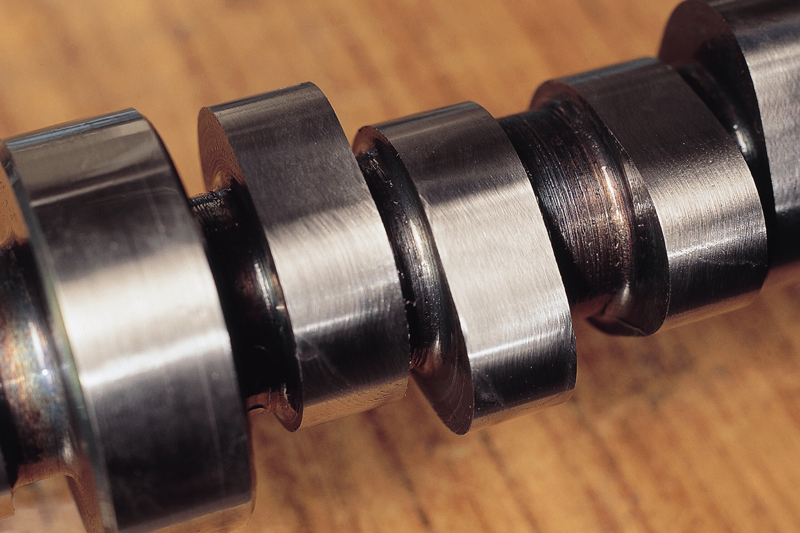
BASE CIRCLE DIAMETER
Think of a cam lobe as a round circle with a lump on the top. This round circle is called the base circle, base diameter or sometimes the heel, and is the perfectly round. When the lifter is riding on this section the valves are completely closed.
The cam’s lobe must be able to fit through the cam bores (the round holes in the block which support the cam and allow it to rotate), which limits the size of lump (lift) that can be added. A way of achieving more lift is to reduce the diameter of the base circle, while not exceeding the inside diameter of the cam bores.
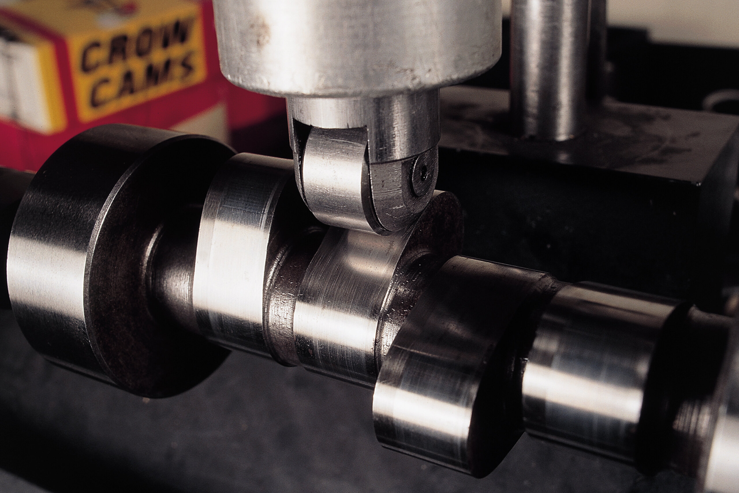
OPENING/CLOSING RAMPS
It’s the job of the opening and closing ramps to ease the valve off and on the seat. Although quick operation is desirable, trying to push things too far will make the engine noisy. Too aggressive and it will be more like a valve being hit with a hammer rather than being pushed so the ramp graduates this process. An overly aggressive closing ramp will also result in noisy valve train and accelerated wear as the valves will slam shut, hammering the seats rather than being eased back to rest.
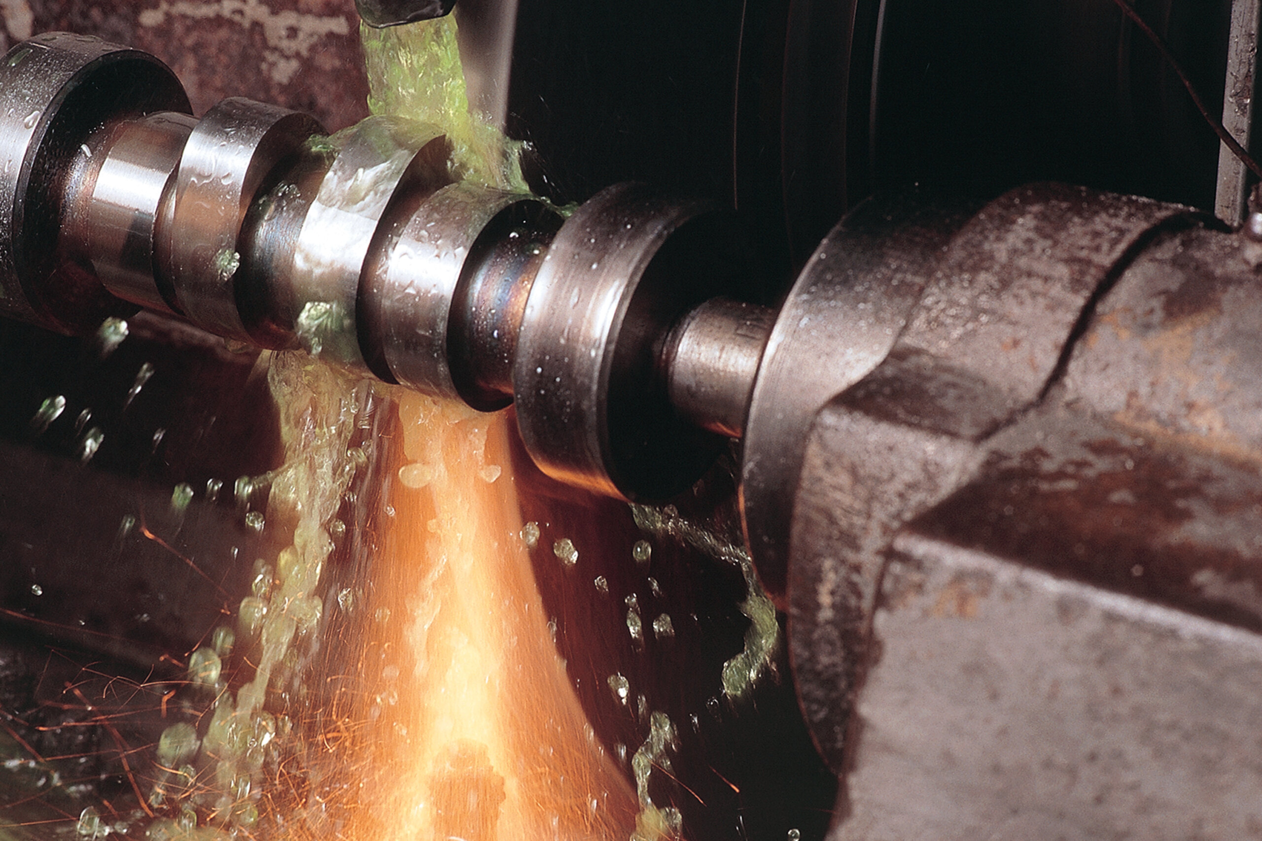
These days, the accuracy with which cams are ground is staggering and miniscule differences in the design of the opening and closing ramps can make all the difference to valve train durability and overall engine performance.
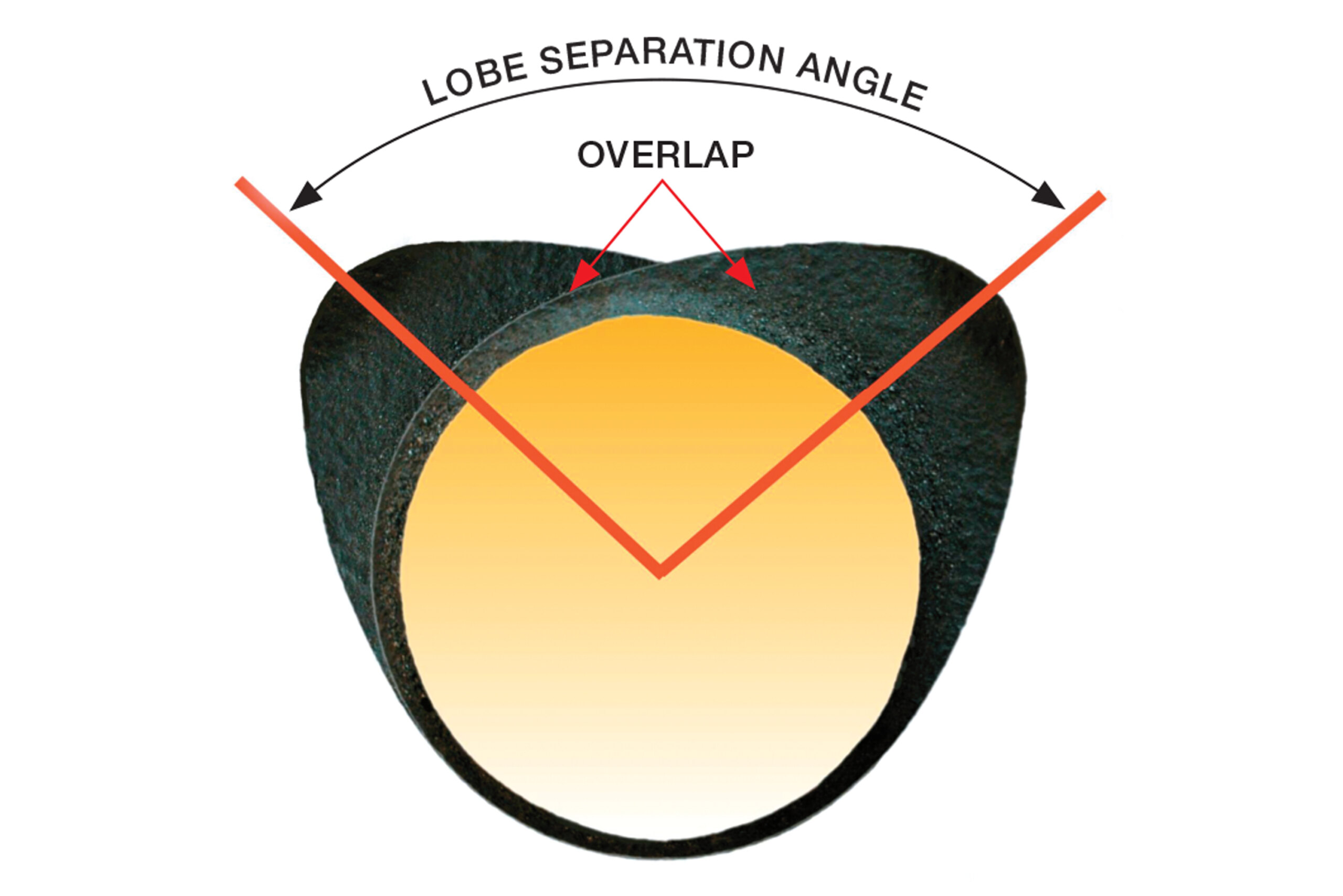
LOBE SEPARATION & PHASING
There are two lobes for each cylinder and the orientation of these in relation to each other along the camshaft is called the lobe separation angle (see above). For optimum cylinder filling, it’s necessary to have both the intake and exhaust valves open for a small amount of time at the end of the exhaust and the beginning of the intake stroke. This is known as overlap and has a significant bearing on performance. In general terms, increasing lobe separation means that the exhaust closes earlier and that the intake opens later. Smaller lobe separation angles increases overlap and generally improves the breathing characteristics of an engine at higher speeds but sacrifices driveability and power at lower revs.
Altering lobe separation moves the lobe noses closer together or further apart. However, the lobes can be moved in the same direction simultaneously by rotating the installed position of the camshaft. Changing the installation position is known as advancing or retarding the cam, which can move an engine’s powerband up or down the rev range by about 500rpm. In general, though, most manufacturers will tell you that if you buy the right cam for your set-up you shouldn’t need to advance or retard it.

FLAT TAPPET VERSUS ROLLER
Flat tappet cams are very basic, with the lifter bearing directly on the came lobe – albeit with oil lubrication. Increasing duration holds the valve open longer, which in turn allows the incoming air/fuel charge more time to enter the cylinder. To increase duration the valve must be opened sooner and quicker, this is done by increasing the angle of the lobe’s flank or opening ramp.
The steepness of this ramp is limited by the diameter of the lifter. Once the angle becomes too steep, the lobe will no longer run on the face/base of the lifter – rather the lobe will hit the edge of the lifter causing considerable damage. Using a lifter with a roller tip allows the use of much steeper lobe flanks. Roller cams are bigger everywhere and offer several performance advantages. Roller cams can open sooner and close later.
HYDRAULIC VERSUS SOLID
Once again it’s all about the lifters. Solid lifters are by definition a round barrel of metal with a fixed base and top (pushrod cup). Valve lash has to be accurately and frequently manually adjusted to minimise free play in the valve/rocker arm/pushrod/lifter assembly. They’re noisy, have lower lifespan and these days are intended for competition purposes only.
For street applications hydraulic lifters have all but phased out solid lifters. Here valve train lash is automatically eliminated by pumping pressurised oil into the body of the lifter raising its centre plunger. Opening and closing ramps are radically different for solid and hydraulic lifters, so you should never use a solid lifter on a hydraulic cam and vice versa.
TIME LINE
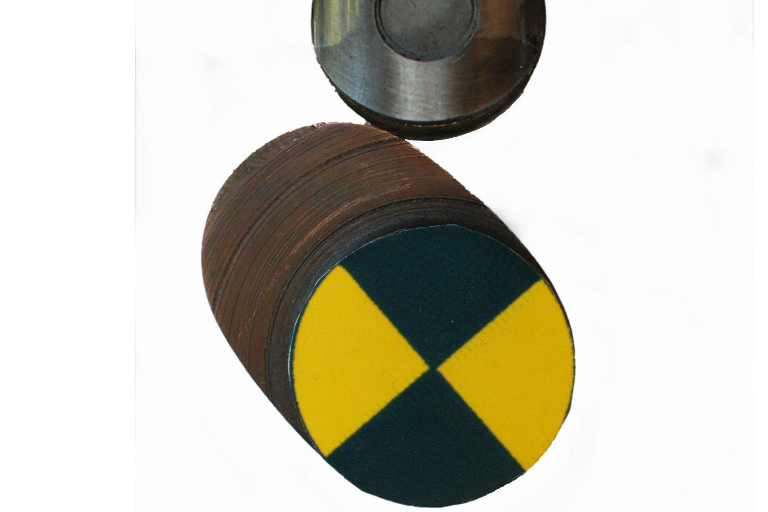
At zero degrees the lifter is sitting on the base circle and the valve is shut. At around 100 degrees the lifter is just starting to rise up on the opening ramp. Much of the lifter movement at this point is taking up any free play (lash in the system). By 120 degrees the lifter is starting the region of maximum acceleration. This acceleration begins to slow when you reach the end of the flank at around 140 degrees. Note how the contact point between the lobe and the lifter base moves from the centre of the lifter out to the edge and then back again as the lobe moves through its rotation.

With the lifter sitting on the nose of the cam (180 degrees) the lifter and valve are at their maximum lift. We haven’t shown the other half of the rotation as it’s just a repeat of the first half – this is known as a symmetrical cam. Non-symmetrical cams have a different opening and closing profile on each individual lobe. Non-symmetrical cams should not be confused with dual pattern cams – where a different profile is used for the separate intake and exhaust lobes.
WRAP UP
The right cam will make or break an engine and grinding them is an exacting science. While many cam manufacturers now use computerised pre-analysis, much of the science is learned through experience and exhaustive testing.
However, the advent of computer modelling can generally show potential problems well before any metal is cut, saving a great deal of time and trouble in the long development process.
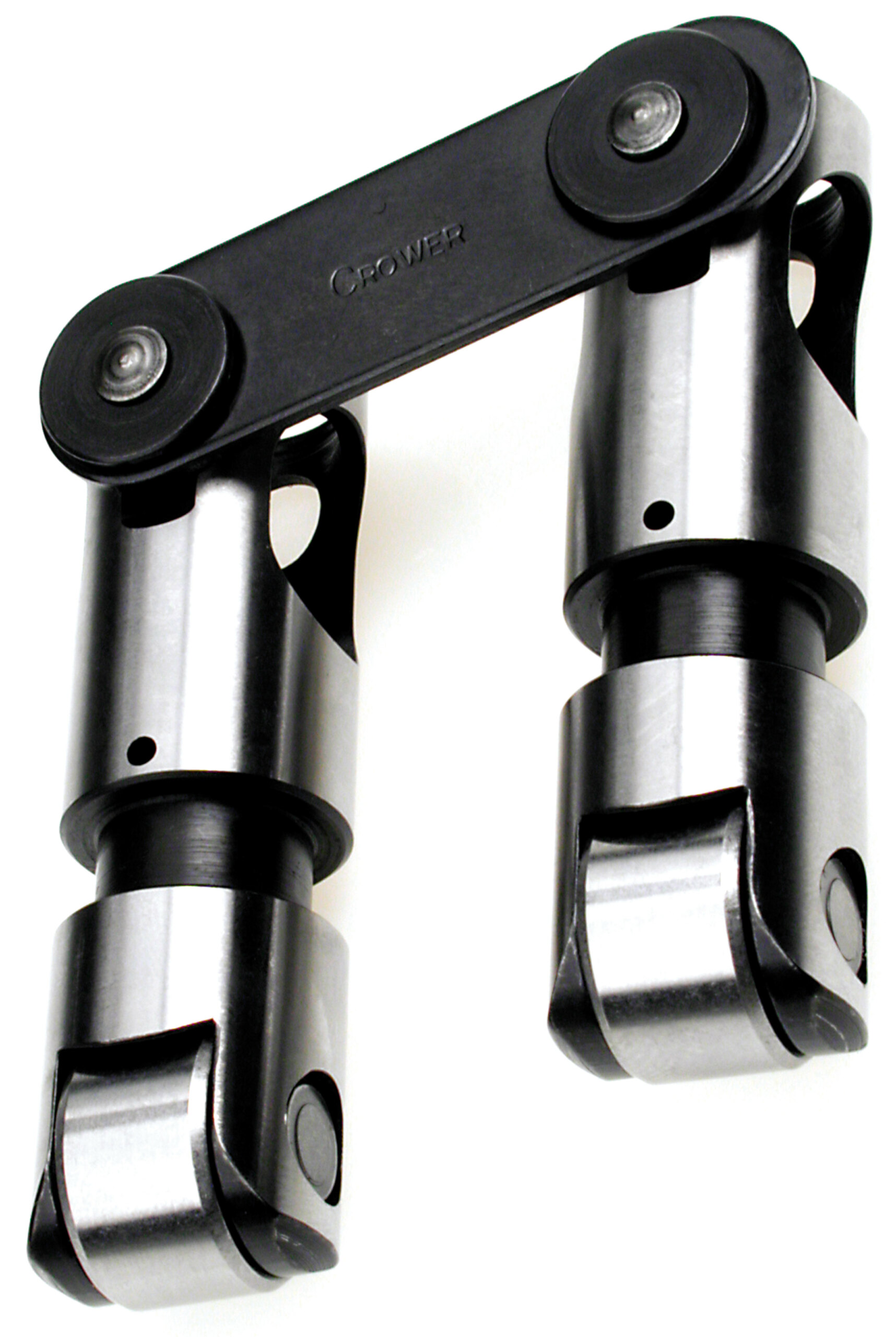
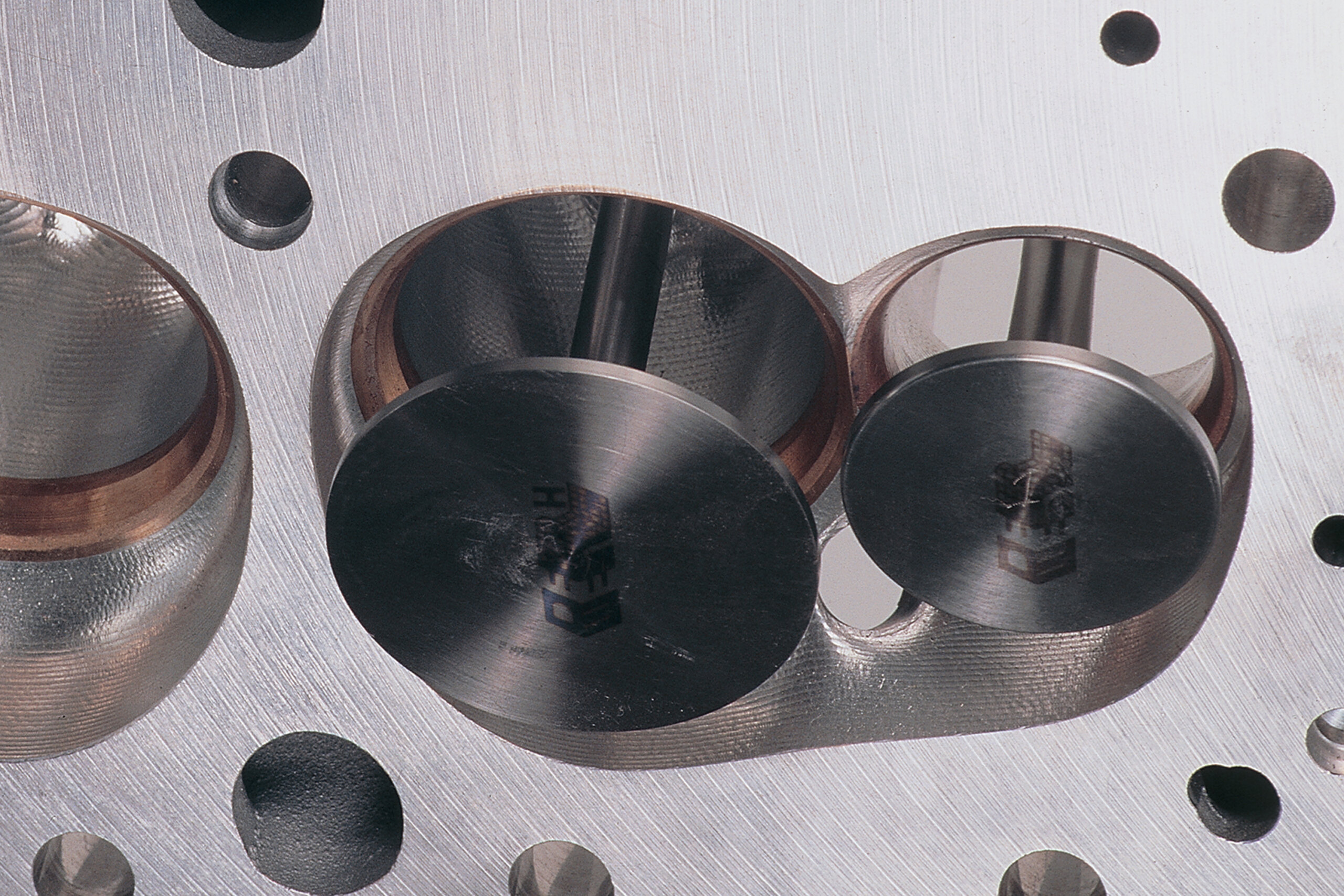
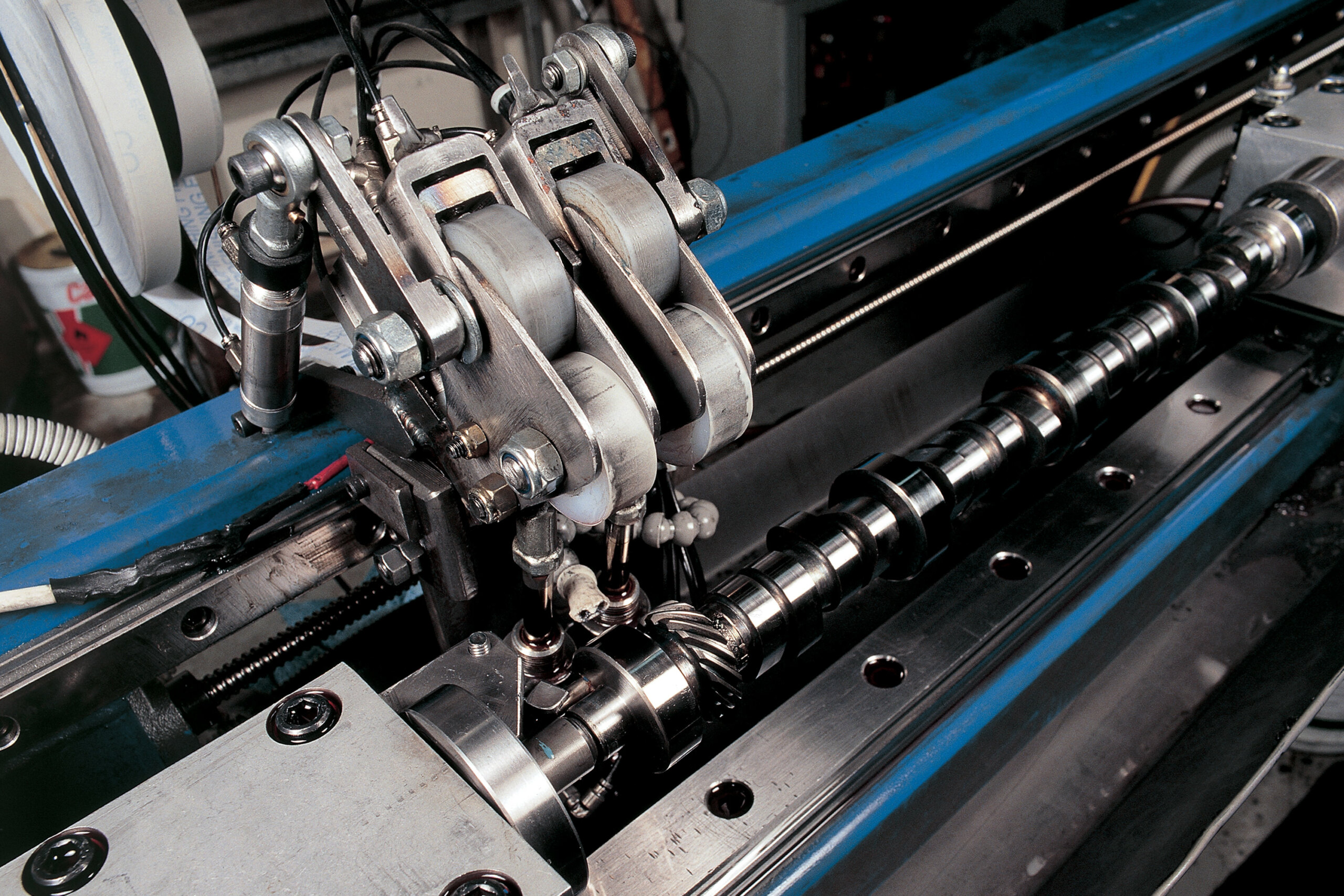
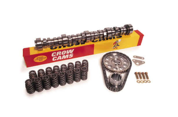
Right: This is typical a roller lifter conversion for engines originally designed for regular lifters. The bridge joining the two lifters is there to stop them from rotating
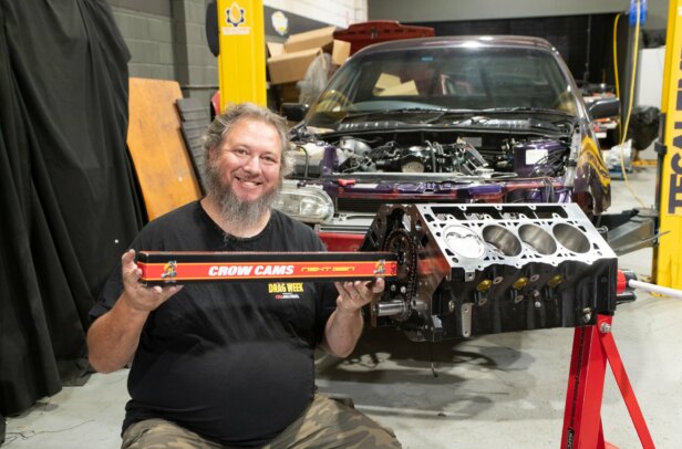
Both the crew from Crow Cams (who supplied the camshafts for us to dissect) and Clive Cams were a wealth of information while compiling this feature.
Comments