
First published in the April 2008 issue of Street Machine
It’s been said that if surfaces could be machined perfectly, head gaskets wouldn’t be needed. Modern CNC machines can achieve tolerances within thousandths of a millimetre but engines still need gaskets. And one thing’s for sure — there’ll come a day when your gaskets will need changing.
While changing a head gasket on a modern multi-valve or overhead cam engine is quite involved, it’s still doable for the home mechanic. However, there will be a number of unique steps, or areas that require particular attention. There will also be certain disassembly and re-assembly procedures that will be unique to any given engine. For this reason you would be unwise to tackle such a job without a quality workshop manual at hand.To give you an overview of some of the peculiarities we’re referring to, we followed along as the crew from Mike’s Dyno Tuning performed a head gasket swap on a Ford BA six-cylinder turbo.
Step-by-step:

1. Changing the head gasket on the turbo six isn’t all that complicated but it is quite labour intensive. Everything that plugs into or is attached to the head has to be unbolted or disconnected. Also, the timing cover must be removed. This requires removal of the harmonic balancer. The balancer’s mounting bolt is very tight; using a Powerbar as shown to loosen it makes life easy.

2. Removing the harmonic balancer is tricky. A special puller suited to the Ford balancer is best but if you’re a clever fabricator you could fashion something like this yourself. This puller is about the only type of special tooling required for the whole job. All in all, the Falcon six is a good engine that’s relatively easy to work on; it’s a shame it’s going to be discontinued.

3. Unbolt the power steering pump and the alternator, disconnect the coolant and oil transfer lines to the turbo and remove the front cover. Slip the lower timing chain sprocket off the nose of the crankshaft, lift the timing chain off the cam sprockets and remove it. Keep track of all bolts and other parts. To simplify reinstallation of the cams and chain, set the engine at TDC No.1 before beginning.

4. It’s extremely important to maintain even pressure across the camshaft retaining bridges during removal and installation. Undo each bolt about one turn at a time, starting at the ends and repeatedly working your way in towards the centre until all the bolts are loose enough to spin out by hand. Although the cams are very similar, they are not interchangeable so don’t mix them up.


5. Remove the rocker pivot posts and rockers, loosen and remove the head bolts in the reverse of the tightening sequence and lift the head off. It may need a tap to crack the seal or you can loosen the head by levering at an appropriate spot. Clean the gasket surface and chambers thoroughly. This preparation is the same regardless of whether it’s an old or a new engine.


6. Use a mounted razor blade to scrape off any gasket residue. A long-handled scraper or spray-on gasket stripper may be needed to remove stubborn residue on older engines — be careful not to scratch or gouge aluminium surfaces. Fortunately, modern gaskets, particularly multi-layered steel types, tend to come off with little trouble. Do not allow any residue to fall into the bores or inlet runners.

7. After everything is clean, set the new gasket in place. Make sure it’s in contact with the block everywhere — that is, make sure it’s pressed down around the head dowels. Ford recommends installation without the use of products like Hylomar or copper coatings. Note that neither the inlet or exhaust manifolds had to be completely removed; they were just unbolted and laid back out of the way.

8. It’s important that the head is lowered carefully into position when reinstalling it onto the block, so get some extra assistance. Also, be careful of the coolant temperature sensor on the back of the head during installation and removal. It’s one of the tricky little things you can miss when searching the head for everything that has to be disconnected and then reconnected.


9. Before being reinstalled, the rocker pivot posts must be ‘bled down’ by compressing them in a vice — use proper soft jaws not a rag over steel jaws. Set the oil hole up so you can see it, then slowly wind the jaws together. Continually wipe away the emerging oil — when it stops appearing you’ve compressed it enough. Reattach the rockers with the clips before putting them back in the head.

10. There are five steps for correctly tightening each head bolt. First, tighten them to 30Nm with a tension wrench, then tighten them through 90 degrees using an angle gauge. Next, loosen them off 90 degrees. Re-tighten them to 40Nm and finally tighten them through 90 degrees again. Work from the centre bolts out to each end evenly. Use new head bolts, which will set you back about $120.

11. Reset the cams in place. Spin the bridge bolts down by finger, then turn each of them one turn at a time until the bridges are in firm contact everywhere along the full length of the bridge. Each of these bolts should then be tightened to 10Nm. Lubricate all components with oil. If it’s to sit for a while before being run, use assembly lube on the lobes and journals.

12. Resetting the camshafts in position is easy. The orange-coloured links are set in position against the blue timing marks on the lower sprocket like this — note that the sprocket is hidden behind the crank trigger wheel. Then slip it back onto the nose of the crankshaft, being careful to keep the chain on the sprocket in this position. Because it’s keyed, it can only go on in the correct position.

13. With the lower sprocket and chain attached correctly, turn the cams so that the orange-coloured timing chain links line up with the blue marks on the cam sprockets. As you do this, make sure that the chain on the drive side (right-hand side in this view) is taut. Also, make sure the timing chain sits between the long tensioner on the left and long guide on the right.


14. To reinstall the cam tensioner, insert an Allen key as shown and fully compress the plunger. Remove the Allen key, let it back out two ‘clicks’ and recompress it — this aligns the lever/plate with the hole in the body. Re-inserting the Allen key keeps the plunger compressed. Once remounted, remove the Allen key and the plunger will spring outwards and apply pressure to the long tensioner.
There she blows

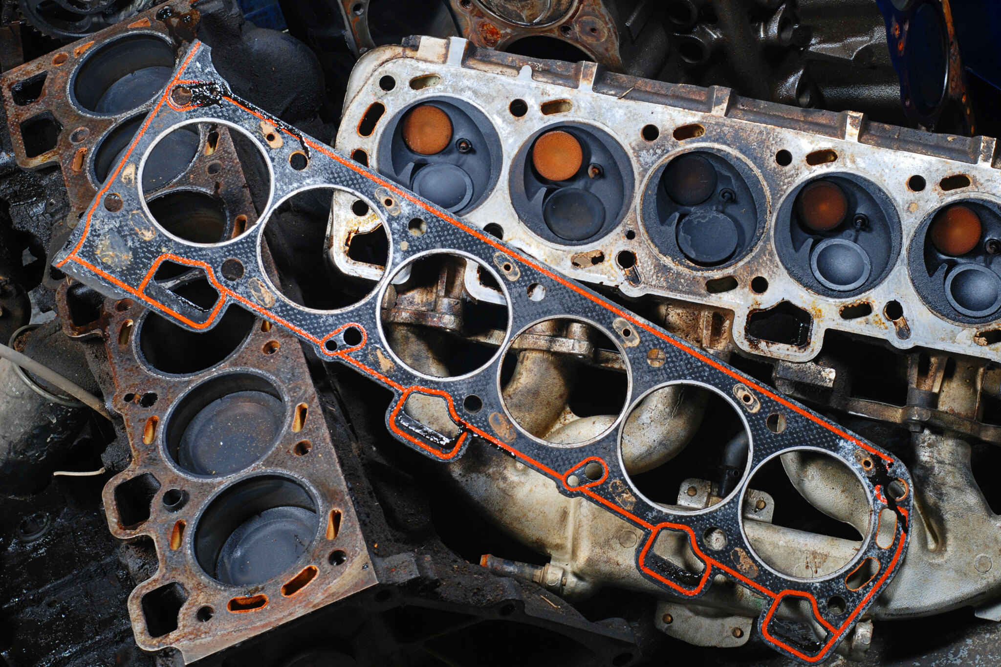
Gaskets get blamed for lots of problems — damaged gaskets are often deemed to be the root cause of a fault. However, it’s more likely the gasket was damaged by something else, so replacing a failed gasket isn’t enough; you need to diagnose the cause of the failure or the gasket will fail again. Detonation, for instance, will hurt gaskets as will electrolysis and corrosion in the head due to not running coolant for extended periods of time. The number-one cause is warped heads due to overheating — it’s extremely common. Use a straight edge to check head and block for straightness and machine if necessary. On the head gasket shown here, you can see how uneven bolt tensions due to a warped head have allowed burning combustion gases to get across the gasket between chambers.
Wrap up

To reinstall the cam tensioner, insert an Allen key as shown and fully compress the plunger. Remove the Allen key, let it back out two ‘clicks’ and recompress it — this aligns the lever/plate with the hole in the body.

Re-inserting the Allen key keeps the plunger compressed. Once remounted, remove the Allen key and the plunger will spring outwards and apply pressure to the long tensioner.

Comments