
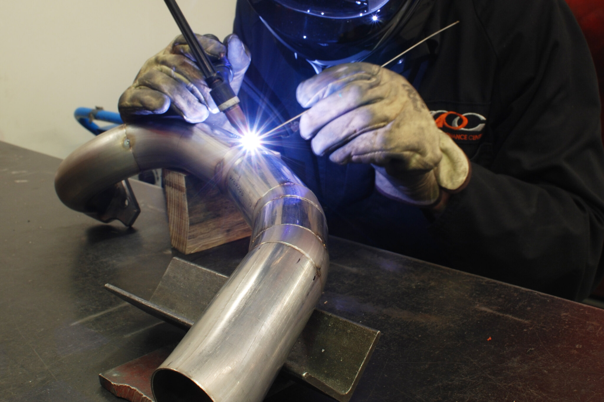
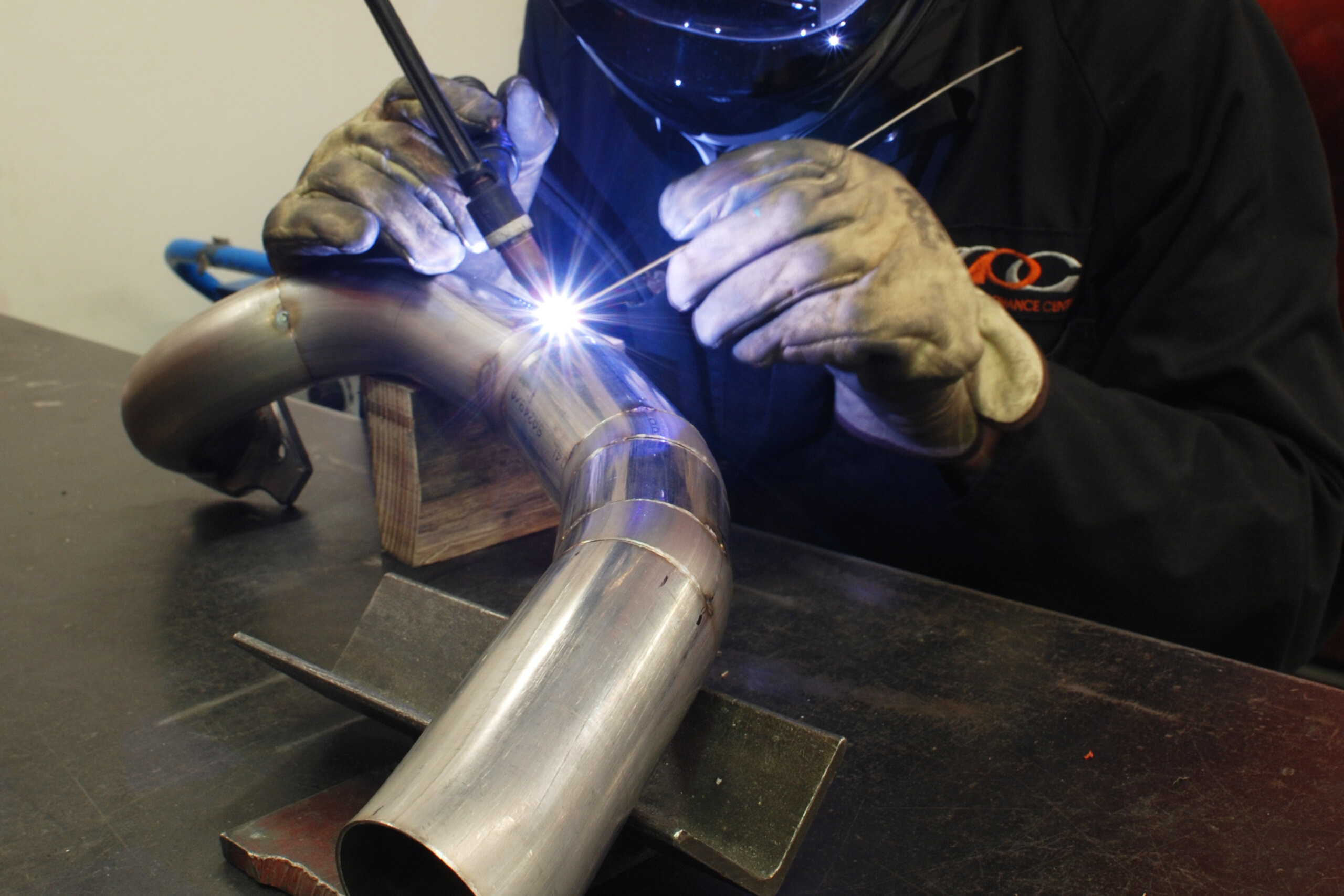
We have previously explained how MIG and TIG welding work and how to get set up. Now it’s time to get going and make some welds. To become a competent all-round welder takes quite some time, which is why a welding trade course takes four years. But hobbyists (us) only need to know about the limited range of things that relate to specific activities, which is a much smaller and easier to master body of knowledge.
The best way to learn how to weld is to watch an expert and look at their results. John Potter from Australian company ASR manufactures performance oil pans (including pans for High Energy), race parts, even whole race cars. In short he’s an expert welder, capable of welding just about anything, and agreed to help us with some tips and examples.
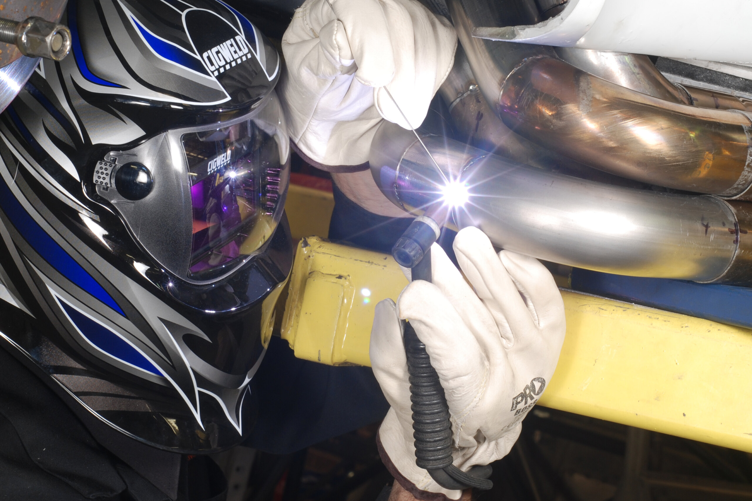
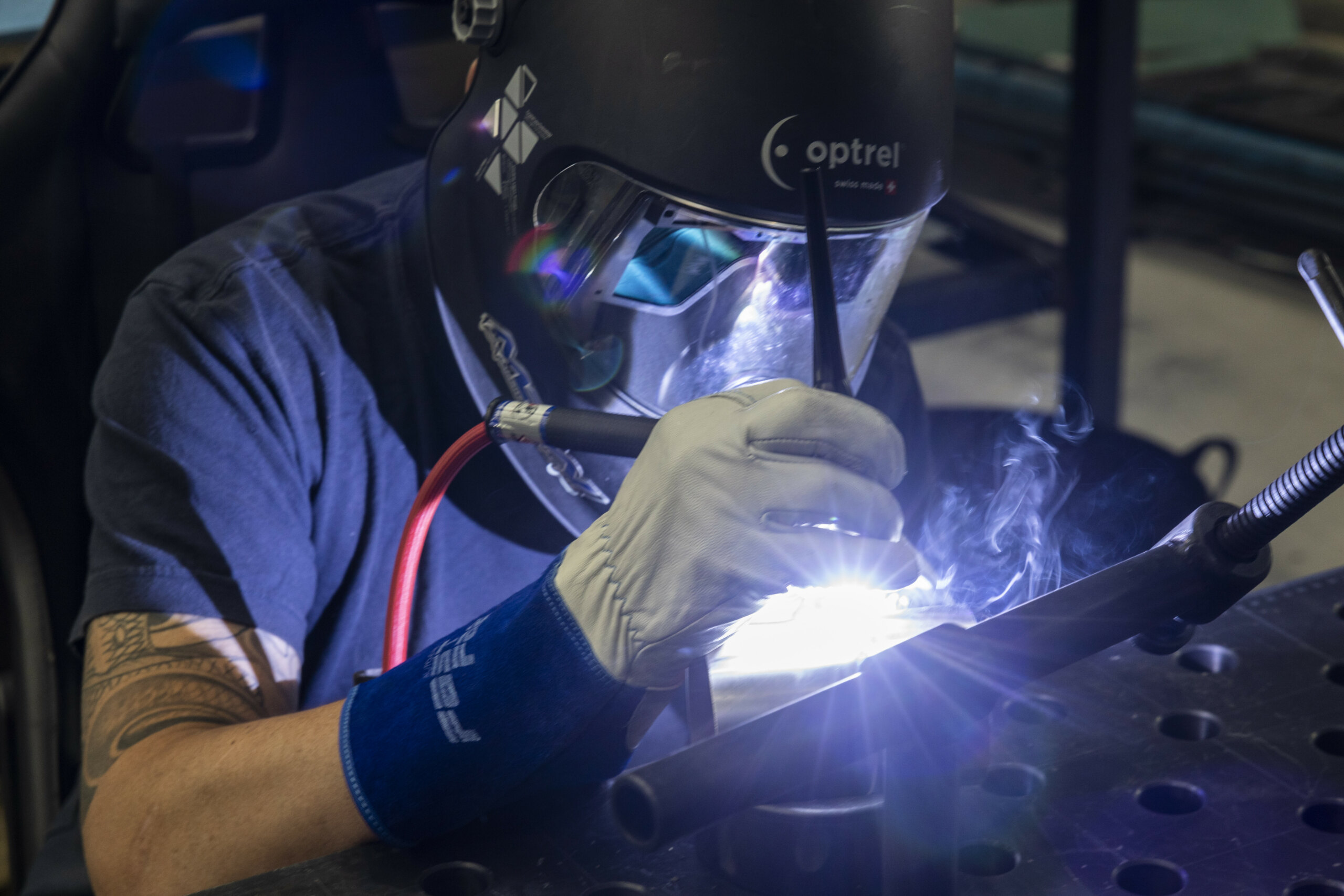
When learning to TIG, it may be easier to practice without filler rod. But using filler rod is part of the process so it’s best to become accustomed to using it as soon as possible.
Make your first welds on 1.6mm (1/16in) mild steel plate. Visit your local steel merchant and rummage through the off-cuts bin. Take some home and start practising; it really is the best way to learn.
Welding is all about getting heat into the metals to be joined. Too much heat generally creates unnecessarily wide welds with a sunken appearance — called undercutting. Look at image D — it looks like the metal has been gouged away right next to the weld. This creates a weak, stressed area. Excessive heat also causes excessive spatter along with orange/brown rust-like deposits. These deposits are gas residue from melting the filler wire at excessively high temperature. Such deposits are usually seen around welds on heavy materials, as the thickness means that adequate penetration can only be achieved using high temperatures.
In the worst case the weld sags so far that the metals involved fall away completely resulting in a hole, or ‘blow through’. You can reduce the heat passing into the metal by reducing the amps, moving the gun faster or a bit of both.
Conversely, too little heat reduces penetration (cold lap) and creates welds that sit high in relation to the parent metals — often referred to as pigeon-shit welds. At their worst, these welds are so poor that they can be broken by hand.
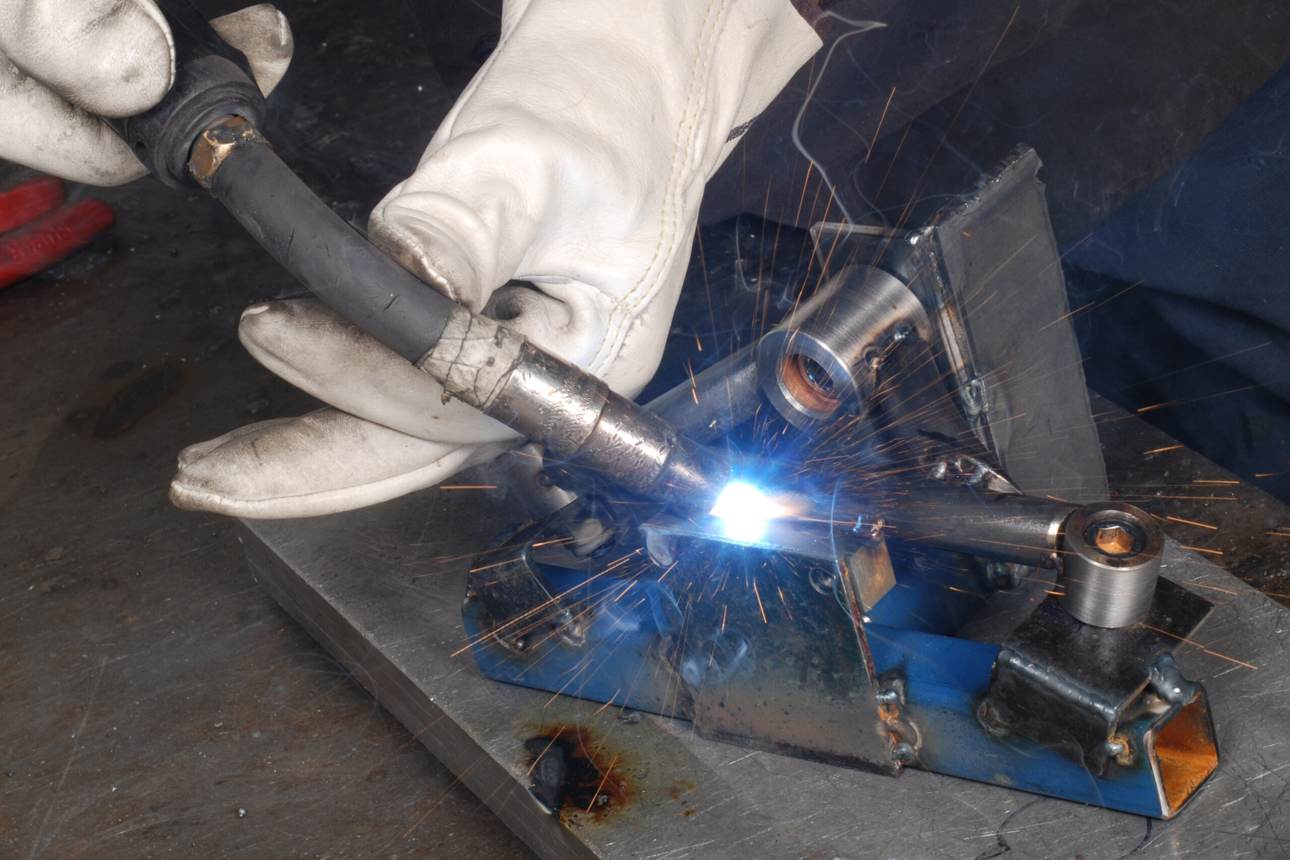
Attempting to weld with a low-amp/heat setting will see you struggle to melt the metal. You’ll stay in one place for too long, putting a lot of heat into the weld despite the settings (Note heat-affected area in Image TIG welds #7). If you try moving too fast on low amps there won’t be any adhesion between the parent metals and filler rod.
In broad terms, an ideal weld bead should sit somewhat higher than the parent metals and there should be signs that the weld has penetrated through to the back of the work pieces. There are exceptions: aluminium TIG welding can display very prominent beading, while the beads on TIG-welded exhaust pipes may barely rise above the surface.
John says that the ideal weld is one that uses the least amount of heat possible to achieve the desired result. While far from ideal, a wide heat-affected area isn’t such a problem in mild steel. However, in chrome-moly and some other metals it can be. The best way of judging how you’re going with this is to look at the following examples.
You can melt aluminium with a DC TIG but it will be a lousy weld because of the aluminium’s oxide surface layer — AC/DC TIGs break away this layer. It’s possible to TIG weld without filler rod, although it’s preferable to use it as it contains de-oxidisers that improve the weld.
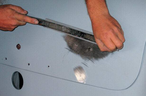
Surface cleanliness is essential so thoroughly remove oil with solvent and wire brush the weld area.
Scraping away a bit of paint to start a weld, then relying on heat to burn off the remainder should never be done — remove it all.
Any welder or other equipment you’re going to use should have a manual that includes a comprehensive safety section. Read it carefully and follow the instructions. Further, every type of welding consumable has a Material Safety Data Sheet (MSDS) or similar safety and handling document associated with it. Read it and follow its instructions. If you don’t have access to such instructions for any equipment or consumables that you’re considering using, don’t use them.
If your welds are just for holding up a shelf in the garage they don’t have to be masterpieces. On the other hand, if you’re welding together a trailer to tow down the road behind your car, things are much more serious. All we’re showing here is how to get started; if you plan to make welds by which your life — or other people’s — will hang, go and take a course and get plenty of practice.
Thanks to Melbourne Performance Centre and ASR for showing us the basics.
MIG WELDS

1. A good weld with correct settings. It was made right to left, as are all the following examples. The bright line down the centre is actually the entry point followed by the wire as it was fed into the molten pool. Lighting makes it look higher than it is — it’s only slightly high.

2. John turned the gas off halfway along the weld. This has created a poor, weak weld with little bonding between the filler and parent metals — it would break very easily. Painted, oily, greasy, or otherwise contaminated surfaces will produce similar results.

3. The first part is a prime example of a poor weld caused by low amps and insufficient wire feed speed. Note excessive spatter along with high-sitting bead and lack of penetration; neither parent metal was adequately melted. This weld would likely fail when stressed.

4. This 90-degree fillet weld exhibits excessive heat due to a high-amp setting. The wire feed was also too fast. Here the heavy liquid puddle has fallen away from the upright section, resulting in pronounced undercutting along the upper edge.

5. This TIG-looking weld is a pulsed-current MIG weld and is very strong. John uses it in sump manufacturing due to the harsh environment. Engine vibration and harmonics can shake a sump to pieces, particularly internal gating and baffling.

6. This is how far your MIG wire should protrude from the nozzle when starting. If it has a ball on the end, clip it off with side-cutters. It’s available up to 1.6mm in solid wire. Flux-cored wire (up to 2.5mm) does not require gas and is good for building bridges
TIG WELDS

1. Higher quality TIG machines use pulsed current. This allows the machine to apply intense heat into the welded joint for increased penetration. However, because the current is pulsed between high and low values, the heat doesn’t build up.

2. Having a large heat-affected zone (bluish discoloured area) is bad as it weakens the metal adjacent to the weld. Note how the affected area extends a considerable distance from this conventional TIG weld. This (and the undercutting) is caused by too high a heat/amp setting.

3. The layering effect in this non-pulse-controlled TIG weld is created by dipping the filler rod in and out of the weld puddle. When you withdraw the rod, make sure the hot tip remains protected in the gas shroud to prevent it from oxidising.

4. A high temperature weld with lots of filler rod and a fairly large heat-affected zone. Despite the fact that it’s not quite spot-on (due to the heat along with the bead, which is sitting a little higher than is ideal, this is still a strong weld.
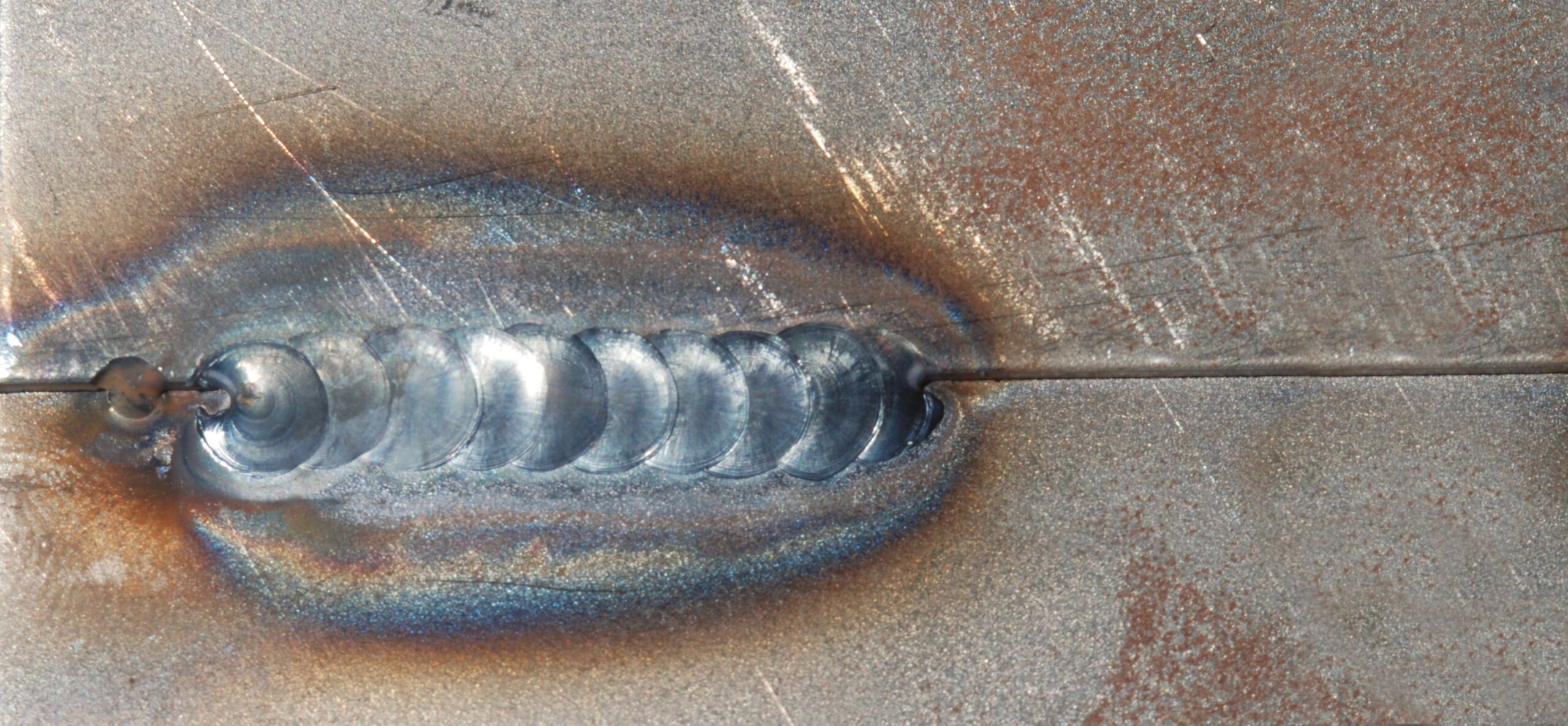
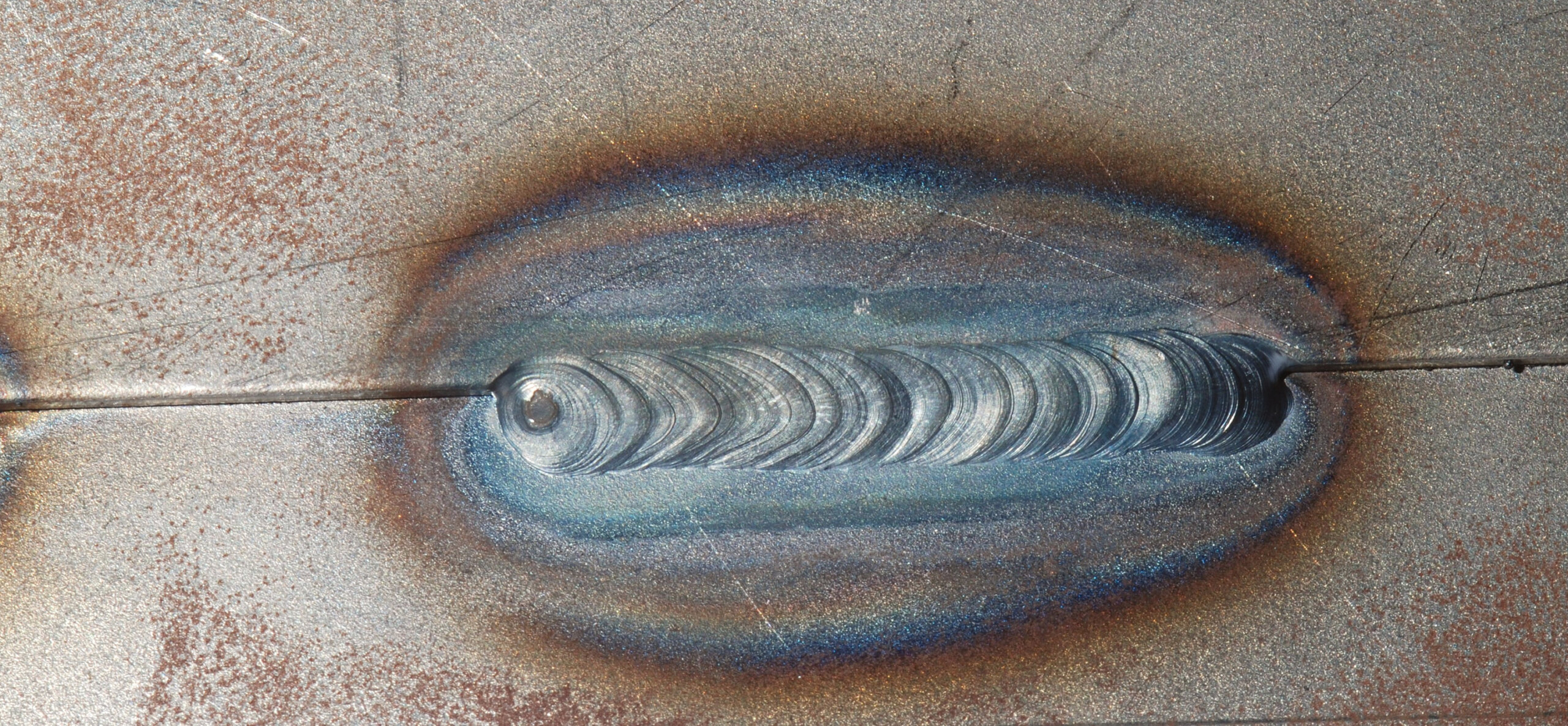
5. On the left is a pulse-controlled TIG weld, while on the right is a non-pulse-controlled conventional TIG weld. Non-pulsed TIG welds are normally the smoother of the two. Note smooth finish of the non-pulsed weld in Image Tig on Aluminium #4.

6. A weld made with a very low amp setting — note the small physical size of the scaling. Low amp settings require slow progression, which means you’ll be applying a lot of heat despite the lower setting. The higher the heat, the faster you have to move the torch.

7. Weld on the left is an example of how a good pulsed TIG weld should look. The weld on the right is also pulsed but no filler rod was used. This has resulted in a weld that’s noticeably undercut and weak due to poor bonding between the two halves.

8. Dirt was rubbed into the joint on the left and the amps were turned down. The weld on the right was done at a really high setting and no gas. Everything about both of these welds is horribly wrong. The high-heat weld looks like a dirty stick weld but it’s actually a TIG!

9. On the left is an example of a good pulsed TIG weld. Sufficient heat and torch speed has resulted in good penetration and minimal heat-affected area. To the right is a poor weld done with overly high amps (large heat-affected area) and very little rod.

10. Weld on the left might not look very good (due to high heat) but it’s a reasonably strong weld. The weld on the right is a different matter; everything is just too low. There’s no penetration and no adhesion between the parent metals and filler rod due to insufficient heat.

11. Some TIG machines have foot controls which allows the operator to adjust the welding current as a weld progresses.

12. John sharpens his TIG electrodes on a belt linisher but a sanding disc works fine. Sharp tip for steel, rounded for aluminium. The lines left by the abrasive grit should run parallel to the length of the electrode; grind them as shown, never at right angles.
TIG ON ALUMINIUM

1. The smoother appearance (note following welds) indicates a non-pulsed TIG weld. Although the operator moves the torch at a constant pace, the beading results from him dipping the filler rod in and out of the weld puddle as he proceeds.

2. This is an acceptable pulsed TIG weld. Although the operator moves the torch continuously, the machine’s pulsing action forms a series of almost individual welds that results in the beaded or fish-scale finish that is common to TIG welds.

3. This is another pulsed weld, done at a high amp setting — note the cratering on the far left (last) bead. The aggressive beading is more defined due to a high heat coupled with a short hit — that is, the filler rod is dipped in and out of the molten puddle quickly.

4. This weld is not pulsed. It was done with the foot controller, so it’s very short and sharp with highly defined beads — and just about everything about it is wrong. You can see that the cratering at the end is so bad that it’s developed shrinkage cracks.

5. At the far right it’s slightly low on amps (slightly raised bead). At the beginning (right), torch speed is a bit fast (making it too cold), resulting in poor penetration. Later in the weld, Mark has slowed down, making the speed closer to ideal — note lack of undercutting.
HOLD RIGHT

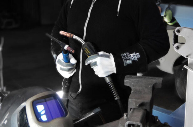
The first thing you have to do is hold the torch in the correct position. For either MIG or TIG torches, that’s leaning back about 15–20 degrees from the direction in which you’ll be welding, as John demonstrates.

A MIG gun nozzle should be between 5mm and 10mm from the job. Note how he’s supporting the gun with his other hand. The electrode of a TIG torch should be perhaps 3mm from the work. The filler rod in TIG welding is held at 90 degrees to the torch. When welding more complex shapes you’ll be forced to vary these ideal positions, yet with practice a good weld is still achievable.
WATCH AND LEARN

Before beginning any welding, we recommend that you undertake some study. Your local automotive book outlet will have a number of highly informative publications. That said, there’s nothing quite like watching an expert demonstrate things.
A range of instructional DVDs have been put together by American car-building expert Ron Covell. We looked at his MIG Welding Made Easy and TIG Welding Basics. Both DVDs are extremely useful, covering all the basics and elaborating considerably on the things covered in this article.

The TIG version even demonstrates how to weld aluminium foil together! If you’ve just invested in a MIG or TIG, get these. There’s a range of metal-working and fabrication titles by Ron — if they’re as good as the MIG and TIG titles you’ll want all of them.
Comments