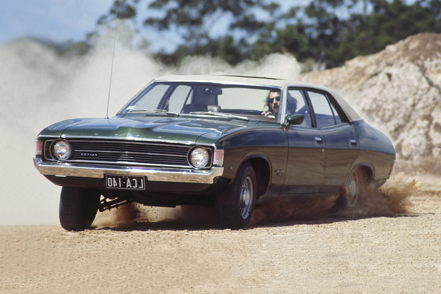
CARS are fine to look at but they’re more fun when you jump in and make them accelerate, brake or corner hard. While it’s the tyres that grip the road, it’s the suspension’s job to link the rubber to your streeter so it can perform to the best of its ability.
This article was first published in the May 2009 issue of Street Machine
Without some type of suspension system, your tyres would skip across the road without much grip, so lets take a look at suspension basics, the advantages of different designs, how their physical attributes relate to your car’s behaviour, and how you can improve things for better grip and handling.
UP FRONT
YOU’LL see one of three basic systems under the nose of your streeter: a solid axle, twin A-arm or MacPherson strut. A solid axle is a beam that links the front wheels. This set-up is common on pre-40s cars; it’s still used in trucks today. It should be replaced with a modern A-arm or MacPherson strut if you want performance handling.
Twin A-arm
The common twin A-arm set-up uses hinged upper and lower structures (arms) that are attached to the body at one end and to the suspension uprights at the other.
The MacPherson strut system uses a single upright element that’s surrounded by a spring and contains the shock absorber. This system debuted in Australia on 1978’s VB Commodore and remains in use. On paper, double A-arms offer better geometry but the excellent handling of many MacPherson strut-equipped cars shows that it can be engineered to work extremely well.
MacPherson strut
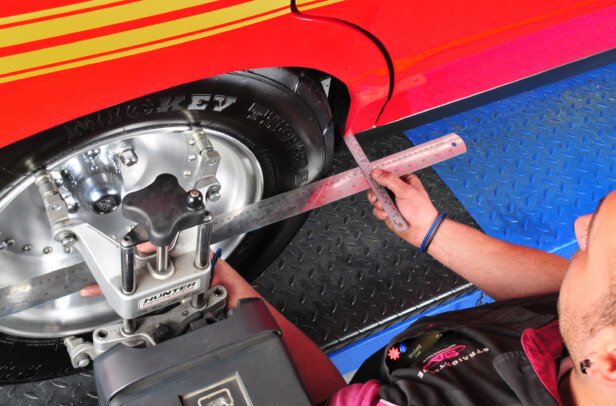
CAMBER, CASTER & TOE
THE angle of your front tyres off vertical when viewed from the front is termed camber. Closer at the top than the bottom is negative camber; positive camber is the opposite. Tyres offer maximum grip when sitting close to perpendicular to the road; in practice, this means a little bit of negative camber is preferred as the outside tyre will stand up straighter when the car leans over while cornering.
On a side view of a wheel, if you drew a line through the top and bottom ball joints it would be at an angle. This is termed caster. A suspension system has positive caster if this line leans backwards at the top. Positive caster causes the front wheels to straighten up when moving forward, enhancing straight-line stability — drag cars run lots of caster. Unfortunately increasing caster increases steering effort.
Caster angle
Toe is easiest to see on an open-wheel racer. Looking down from above, toe-out is the condition when the fronts of the tyres are further apart than the rears — toe-in is the reverse.
Toe-in makes a car more stable, while toe-out encourages the initiation of a turn. Toe-out also makes the car wander, so street cars generally run with toe-in, making them easier to drive in a straight line, while racers sacrifice stability for sharper turn-in. Excessive toe-in or out will lead to excessive tyre wear.
SCRUB RADIUS
WHEN viewed from the side, our imaginary line that runs through the upper and lower ball joints forms the caster angle. However, when viewed from the front it forms the steering axis or kingpin inclination — even though cars no longer have kingpins. When looking front on, if the line slants inwards at the top, that’s positive kingpin inclination. With positive kingpin inclination (most passenger cars) this line would reach the ground at a point outboard of the centre point of the tyre’s contact patch. The distance between these points is known as the scrub radius. Scrub radius means that the tyre doesn’t pivot about its centre when being turned; rather it traces an arc. Positive scrub radius works with caster to add feel and assist the self-righting tendency present in all well-designed steering systems. Too much scrub radius leads to high tyre wear and heavy steering.
Kingpin inclination
BUMP STEER
IT IS vital to recognise that virtually all suspension arms, links and elements move in arcs. Analysing the ways in which these arcs interact is fundamental to understanding suspension systems. Steering tie-rods are a good example. If they move in different arcs to the steering arms (attached to the stub axles or uprights) they will tug at the steering arms and turn the wheels, most notably during upward suspension movement, hence the term bump steer.
In this particular set-up, moving the steering arm mounting points at the end of the rack in or out adjusts bump steer
It’s virtually impossible to eliminate it completely and cars are very sensitive to excessive bump steer so it should be reduced for good handling. Bump steer is a problem with some aftermarket steering conversions, especially left to right-hand drive and some rack and pinion conversions — they have a nasty tendency to move off-line (without moving the wheel) when cruising the highway.
Melbourne Performance Centre is modifying this LJ Torana front end for Targa-style competitions. Both control arms have been boxed to improve rigidity, while a race-style rack has been added to sharpen steering response and allow bump steer adjustments
ACKERMAN
DURING a turn, the inside wheel should turn further than the outside wheel. This is achieved either by setting the steering arms attached to the uprights at mirror angles to each other (rather than having them longitudinally aligned with the car) or by setting the steering rack/drag link assembly ahead of or behind the attachment points for the outer ends of the tie-rods. This means the tie-rods will be angled forward or backward so their ends will move through differing arcs and turn each wheel by a different amount. For small steering inputs the difference isn’t very great but as the steering input increases, the difference in the angle through which each wheel turns also increases. This reduces the load on the outside front tyre and is known as the Ackerman angle.
This HQ Targa car has had its rear end redesigned to accept a parallel four-link system with a Watts link — serious stuff
AT THE REAR
STICK your head under the back of your streeter and you’ll find either a traditional diff (known as a solid or live axle), trailing arms or independent rear suspension (IRS). Apart from some pre-40s designs, solid axles fall into three categories determined by how they’re attached to the car. Leaf springs locate the diff transversely as well as forming the spring system, while multi-link suspension systems use separate coil springs. Most simple of the multi-link systems is the HQ/Torana-style ‘triangulated four-link’ system, where the top arms are angled to provide lateral location for the diff housing. From there you go to traditional four-bar systems in which the bars run parallel to the centre-line of the vehicle. This design requires a separate link to prohibit lateral movement, most commonly a Panhard bar or Watts linkage.
Panhard bar
A Panhard bar is a rigid bar that pivots at both ends; one end attaches to the diff housing while the other attaches to the body/chassis. Obviously the end of the bar will travel in an arc, creating a small amount of sideways movement as the suspension travels up and down — the longer the bar the less the sideways movement. A common method of lateral location in four-bar drag racing set-ups is to run a diagonal link from corner to corner of the lower arms, from the rear pivot of one link to the front of the other. Another popular drag racing set-up is to run a short pivoting link from the top of the diff across to the chassis rail.
Triangulated four-bar system
The Watts linkage, as used in V8 Supercars and XE to EL Falcons, is more complex but doesn’t suffer the sideways motion of the Panhard rod. Looking from the back of the car, a Watts link looks like an elongated Z. There are long upper and lower traverse arms, each of which is attached to the body/chassis at its outer end, and to the upper or lower end of a vertical link at its inner end. The vertical link pivots on a central pin attached to the diff housing. As the suspension moves up and down it squashes the Z. It can also be mounted in reverse like the V8 Supercars, where the vertical link is mounted to the body and the horizontal links to the diff housing. This allows them to quickly tune the rear by moving the pivot point of the vertical link up or down.
Watts linkage
A variation of the four-link is the ladder-bar set-up. Here, the upper and lower links actually join at the front in one single pivot point. Ladder bar suspension works fine when the suspension moves up and down as a whole but suffers binding when the car leans to one side (when cornering), which makes it perfect for drag racing but unsuitable for street cars.
Ladder bar
The good thing about a live rear axle is that the wheels stay upright during cornering. However, live rear ends are heavy and if one wheel hits something in the road, it affects the opposite wheel.
Four-link
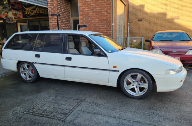
IRS
THE advantages of independent rear suspension (IRS) are that it has considerably less unsprung weight, isolates the wheels on either side and can be set-up to induce a little bit of roll understeer to help the car turn in. However, it can introduce geometry problems of its own. True IRS is similar to twin-arm front suspension in that it has an upright (to which the wheel is bolted) connected to the car by two pivoting links (arms). Most cars that claim to have IRS are actually a swing-arm set-up. In a swing-arm arrangement, the rear hub/stub-axle is rigidly fixed to a single pivoting (swinging) control arm — all IRS Commodores fit into this category.
Unlike most swing-arm IRS systems, the rear suspension in this GT40 replica from Roaring Forties is a fully independent design with discrete upper and lower control arms just like a double A-arm front end set-up
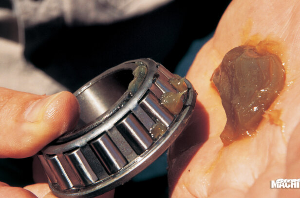
SPRINGS
THE body of your car requires a flexible link to the suspension to hold it off the ground — coil or leaf springs are the main options. Spring rate is the amount of compression that occurs per unit of force applied. Choosing the correct spring rate (and matching shock absorbers) is an important factor in determining how well your car will handle.
It’s easier to consider leaves as one solid leaf rather than multiple leaves. During bump, the body and the axle tube try to flatten out the spring but the arch in the spring tries to maintain its shape.
Several factors determine the rate of a leaf spring. Making the leaves thicker or wider or increasing the arch increases the spring rate, while making the leaves longer reduces spring rate. When you lower a leaf spring (make it flatter) you need to add additional leaves to maintain or increase its spring rate.
The three main criteria for determining spring rate are coil pitch, wire diameter and overall coil diameter. Spring stiffness should be increased as bump travel is reduced (when you lower your vehicle)
To understand coil springs, look at one coil at a time. As the coil compresses, the round bar from which it’s made actually twists. The three main factors determining the stiffness of a coil spring are coil pitch, wire diameter and overall diameter. The number of coils per unit of spring length is known as the pitch and the greater the pitch, the higher the spring rate. Springs are wound from wire; the thicker the wire, the greater the spring rate. As overall coil diameter decreases, spring rate goes up. To understand why, look at the coil side on — each coil looks like a lever. To achieve the same amount of compression the ‘levers’ on a small spring have to twist further than the ‘levers’ on a big spring. The springs used in coil-over set-ups are quite thin compared to factory-style coils, yet they can be up to 200 per cent stiffer!
SPRING RATE
YOU’RE driving down the road and you hit a bump; energy is transferred into the suspension, moving the wheel up — it’s the spring’s job to absorb this energy. However, since there’s only so much suspension travel, at the end of this movement is a pliable bump stop to prevent the metal suspension components smashing into the metal of the car. You want the springs to halt suspension travel before it hits the bump stop because suspension isn’t suspension once it’s sitting hard against the body.
If your car has four inches of travel and you lower it two inches, you need to increase the spring rate so that the springs can arrest suspension travel in this shorter distance. Any suspension expert who tells you they can noticeably lower your car and maintain the original ride stiffness is full of it. If you attempt this, what happens is the suspension continually bottoms out and when that happens, astronomical forces are applied to the body’s structure because there’s no spring travel to absorb the energy. Left like this, the car will tear itself apart over time.
SHOCK ABSORBERS
A SPRING will happily absorb the kinetic energy of the wheel and suspension components. But springs dissipate their stored energy by repeated bouncing. This would not only be quite uncomfortable but the energy from one bump would never be fully dissipated before you hit the next bump. The answer is the shock absorber or damper. The shock absorber accomplishes its task by absorbing energy fed into the spring and converting it to heat that can be dissipated off into the atmosphere.
For optimum performance, shock absorber valving must be precisely matched to spring rate otherwise the shocks will be incapable of adequately controlling the spring
A shock absorber consists of a main body full of oil, out of which extends a shaft which is attached to the car. At the end of this shaft inside the body is a piston with holes drilled in it. During compression, this piston pushes against the oil; the number and size of the holes dictate the rate at which oil can flow through the piston. More or larger holes allow faster transfer, creating less resistance. Smaller or fewer holes restrict oil transfer, creating greater resistance. The greater the force applied, the greater the resistance to oil transfer.
There are actually two sets of holes in each piston — one for compression (bump) and the other for extension (rebound). Each set is covered by spring discs that act as valves. Changing the size, number and stacking order of the spring discs alters the characteristics of the shock absorber. On some high-end shocks, the valving characteristics can be adjusted externally to tune suspension behaviour.
SPRUNG WEIGHT
UNSPRUNG weight is any mass not supported by the springs, such as wheels and tyres, while sprung weight is everything supported by the springs, including body, chassis and passengers. You want to keep unsprung weight to a minimum. If you’ve ever driven in a heavy limousine, you’d have noticed that regardless of how big a bump you hit, you hardly notice it inside. That’s because compared to the weight of the vehicle, the weight of the suspension is small so it can absorb the energy of hitting a bump without disturbing the rest of the car. The lighter the car, the lighter you want the suspension, to make sure the tyres stay firmly planted on the road while body movement is minimised.
CENTRE OF GRAVITY
AS YOUR car rounds a corner it wants to roll, which causes weight transfer. That forces the outside tyres to carry more load than the inside tyres, creating a net reduction in grip. The difference between your car’s centre of gravity and the height of its roll axis causes body roll.
The centre of gravity (or centre of mass) is the theoretical single point from which you could suspend your car at any orientation without it trying to rotate and right itself. In a passenger car, this point is usually just forward of the middle of the car at about camshaft height — exact position varies from car to car.
During body roll, each end your car’s suspension pivots around a point called the roll centre, which is determined by the angles and mounting points of the various suspension components. The roll axis is an imaginary line that runs between the front and rear roll centres. It’s along this axis that the body rolls when cornering.
So what does it all mean? Well it’s incredibly complex, but here’s a simplistic description of the relationship between weight transfer and force transmission. Designers use a low roll axis to make the car more stable, typically lower than the centre of gravity. The distance between the centre of gravity and the roll axis acts like a lever and causes body roll. Shortening this distance results in less body roll; lengthening it makes things worse. Lowering the ride height is one way of moving the centre of gravity closer to the roll axis but this also affects the positions of the front and rear roll centres, and consequently the roll axis angle — due to differing geometry, lowering the front and rear by similar amounts affects the front and rear roll centres differently. And changing the angle of the roll axis can have diabolical handling consequences.
ANTI-ROLL BARS
ONE way to limit body roll is to fit stiffer springs and shock absorbers — at the cost of a harsher ride. A better option is an anti-roll bar. Roll bars roughly resemble a very wide U. The long central section is attached to the body of the car while the ends are attached to the suspension arms. When both sides of the suspension move up and down together the bar simply pivots in the body mounts. However, when one side of the suspension moves up and the other side is moving down (body roll during cornering), opposing movement of the end arms causes the bar’s wide central section to twist in its mounts and act as a torsion spring to resist body roll. It takes the force applied to the outside tyre and uses it to push the car down on the other side. Increasing the thickness of the bar or shortening the end rams increases its stiffness.
CONCLUSION
‘How To Make Your Car Handle’ by Fred Puhn
WE’VE barely scratched the surface of suspension here.
For an in-depth look, grab a copy of:
– How To Make Your Car Handle by Fred Puhn;
– Competition Car Suspension by Alan Staniforth
– or Chassis Engineering by Herb Adams.
We also spoke to Advantage Suspension (03 9555 2633), Roaring Forties, Melbourne Performance Centre (03 9761 7775) and RRS (02 9907 3755) in assembling this story.
Comments