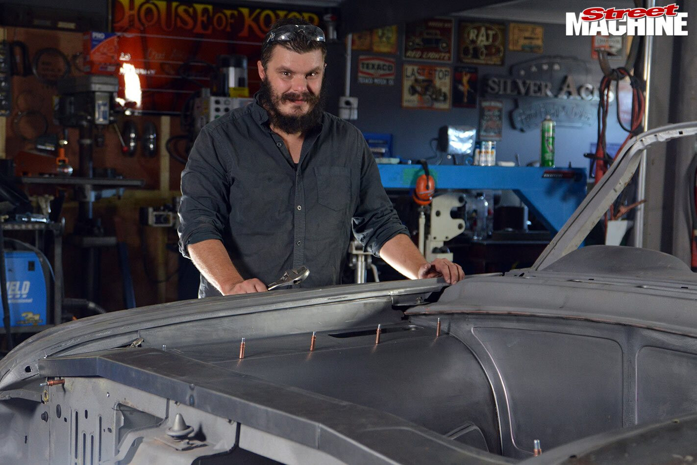
FOLLOWING on from last month’s column on how to fabricate a flat firewall, we now turn our attention to fabricating a pair of inner fenders to complete a silky-smooth engine bay. Again, this isn’t so much a ‘how to’ guide as it is a little insight into the thought process and metal fabrication required for a job like this.
This article was first published in the April 2020 issue of Street Machine
STEP 1.
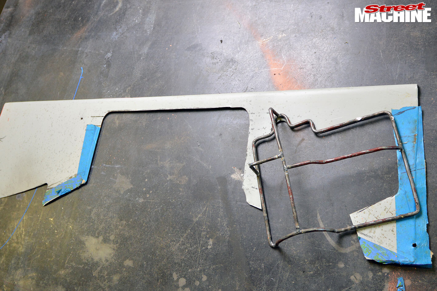
The rod frames we fabricated for the firewall design last time now come in handy as a guide to see where the new panels will sit.
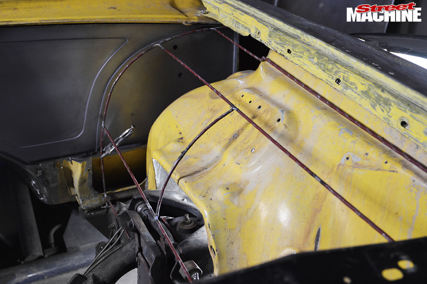
Some scrap 0.6mm steel sheet serves as a template to get a correct line on the bottom edge. Decent card coupled with masking tape also comes in handy for this sort of work.
STEP 2.
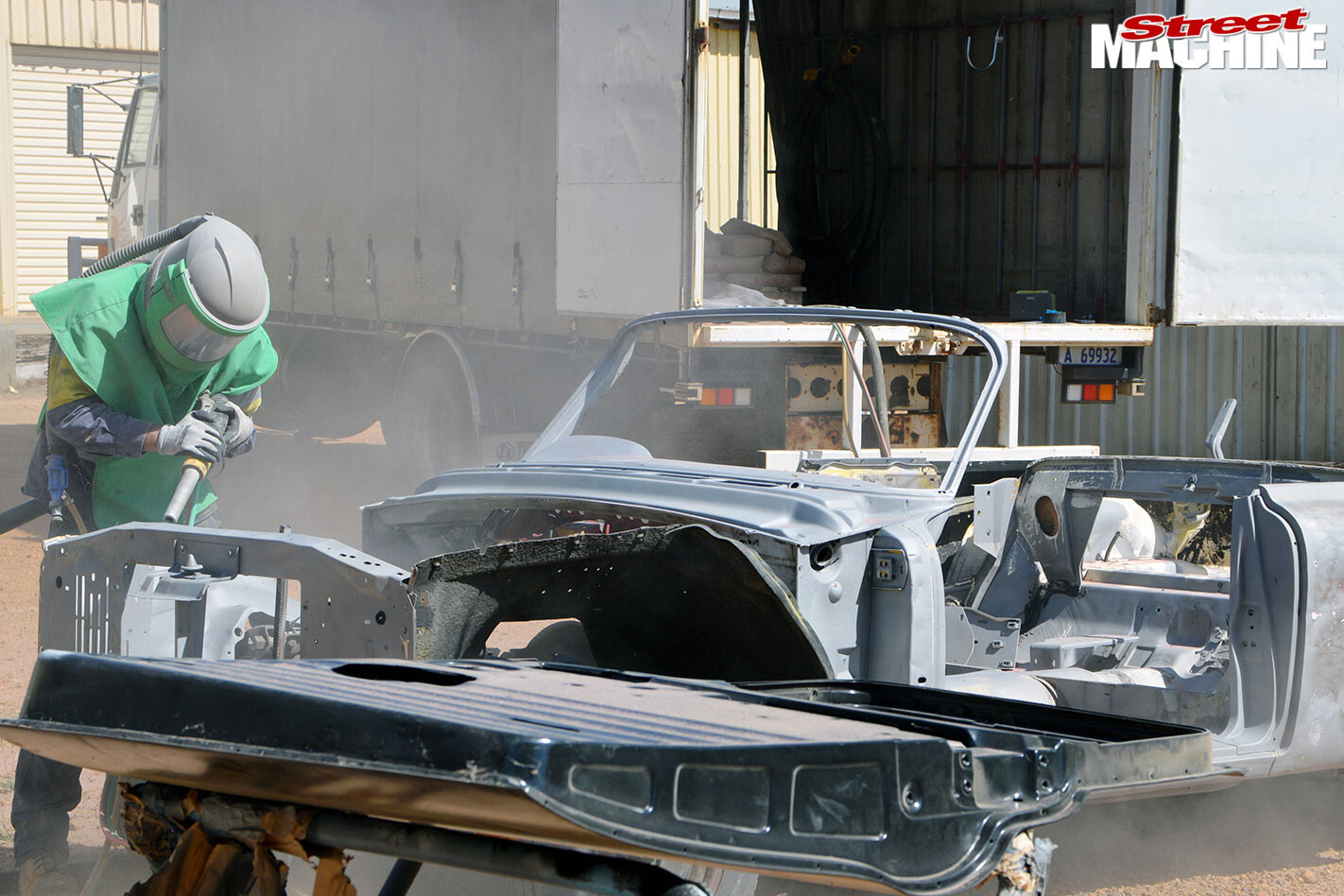
A much-needed visit from the blaster sees things taken back to bare metal, making the bay much easier and a whole lot nicer to work on. Once blasted, everything is coated in Oxytech’s Easy Phos to prevent surface rust.
STEP 3.
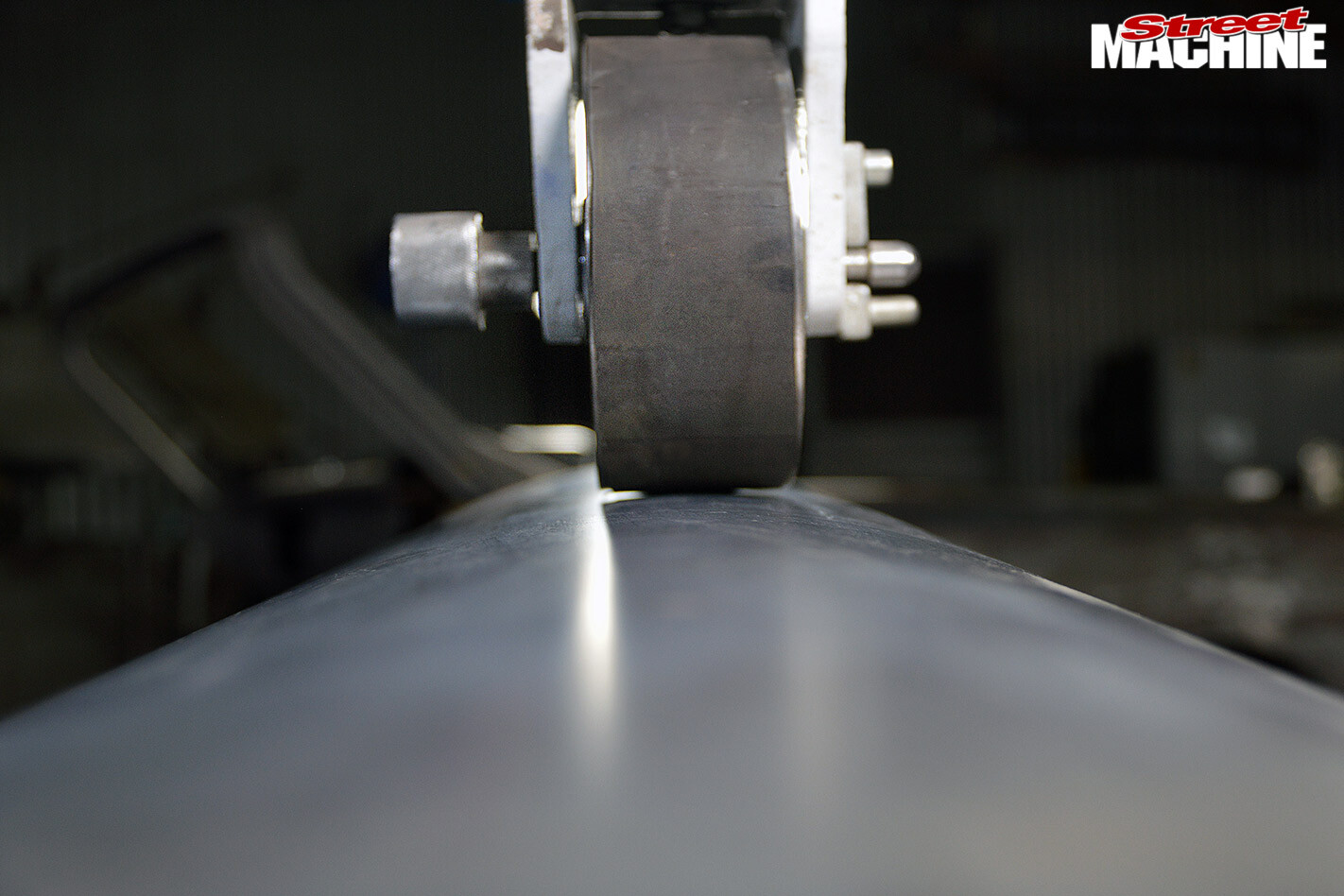
With all the necessary templates in hand, things can now be marked out onto a sheet of 1mm steel. The sheet is then cut out and rolled to give it the appropriate curve. This can either be done using a set of sheet-metal rollers, or by using the English wheel with a rubber band on the top wheel. The rubber band will ensure the sheet can only curve left and right, as opposed to the normal situation of left to right and front to back.
STEP 4.
Now that the wheeled inner fender matches the lines previously rolled on the firewall, some ends or flanges can be added. Again, this can be done in a few different ways; you could tip the ends with a bead roller and use the stretcher/shrinker to bring everything into place, or simply cut a shape to suit. The second method is the one we went with, using a TIG. Fuse-welding along the 90 is a relatively quick process.
STEP 5.
When marking and cutting the sheet, an extra 20mm lip is left all the way along the lower edge. This is now folded over at 90 degrees, with any missing edges filled in and welded.
This is for added rigidity and to give the bottom edge a more finished look where it runs along the chassis.
STEP 6.
A step-down is added to the top edge of the main inner fender.
This can be done with a pan brake (bender), or by running it through the Pullmax with a set of step dies, as shown here.
Again, this is for rigidity and added strength. As you will see, these inner fenders will be a two-piece-per-side deal.
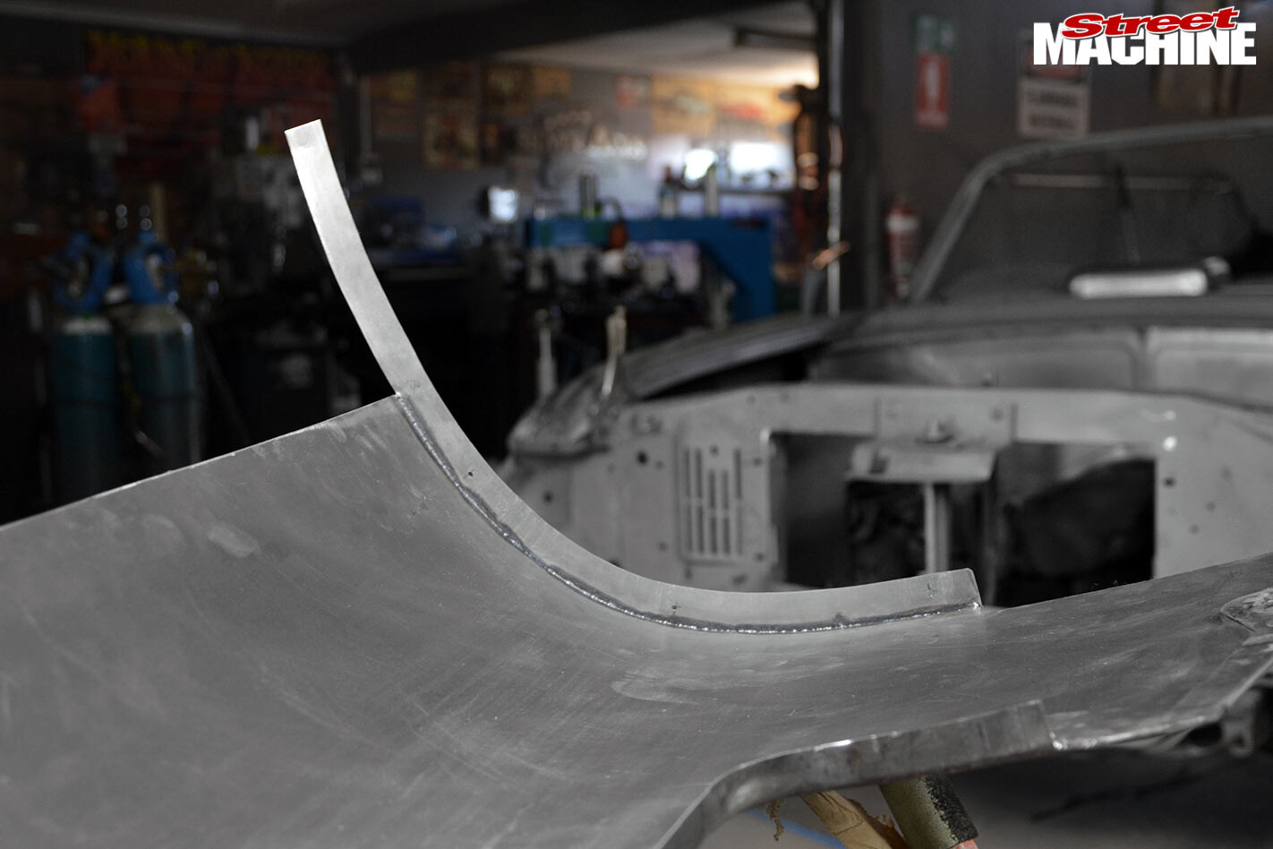
STEP 7.
Overlapping the new, yet-to-be-fabricated upper skirt section straight to the fender was never going to cut it. The edge of the fender with the bolt holes is cut away, and a stepped piece with a gradual curve (front to back) is fabricated with the Pullmax and welded in place of the former factory set-up.
STEP 8.
With the new lower skirt section mounted and secured into its final resting place, you can see the gap that requires the fabrication of a second area of skirt. Some 0.6mm sheet is mocked up as a template, then transferred over to 1mm to be used for the final piece. This two-piece design allows for bonnet hinge, headlight and grille mount access, and will blend into a new upper radiator support panel. Clean lines and seams give the engine bay the ‘industrial’ feel we are after.
STEP 9.
A small amount of curve is applied to the 1mm sheet using the wheel; some detail with the bead roller can then be added, followed by a few bends and a 20mm flange.
The upper flange of the top skirt section has a slight curve front to back that follows that of the fender. This is tipped over in the bead roller. This flange and the lower one are then sealed with epoxy before being folded over onto themselves.
This gives us a thick, sturdy surface to run countersunk mounting hardware through. After a trial-fit with Clecos to hold things in place, we look to be heading in the right direction.
STEP 10.
The upper radiator support was mocked up for the upper skirt placement and design before fabrication had started – another one of those ‘think five steps ahead’ situations.
Now that both sides are complete and symmetrical, a cover for the upper area of the radiator support panel is added.
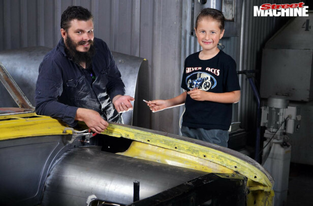
STEP 11.
A pair of upper control arm covers is made to tidy things up further.
Loose ends such as the lower skirts to the firewall and under-dash booster are all finalised.
WRAP-UP
There you have it – an insight into what’s involved in fabricating a custom engine bay. The design of this type of job is limited only by your creativity, so crack out the tools and have a go!
Comments