Owning a classic muscle car is great but it can end up looking pretty much the same as all the rest. Rock up to any V8-orientated show and you’re bound to see rows and rows of Holleys on Edelbrocks perched between polished alloy rocker covers.
First published in the December 2010 issue of Street Machine
There’s nothing wrong with that; classics earn the title by celebrating the technology and feeling of the time in which they were made. However, doing something that stands out as a bit different while maintaining that classic look and feel can be more interesting.
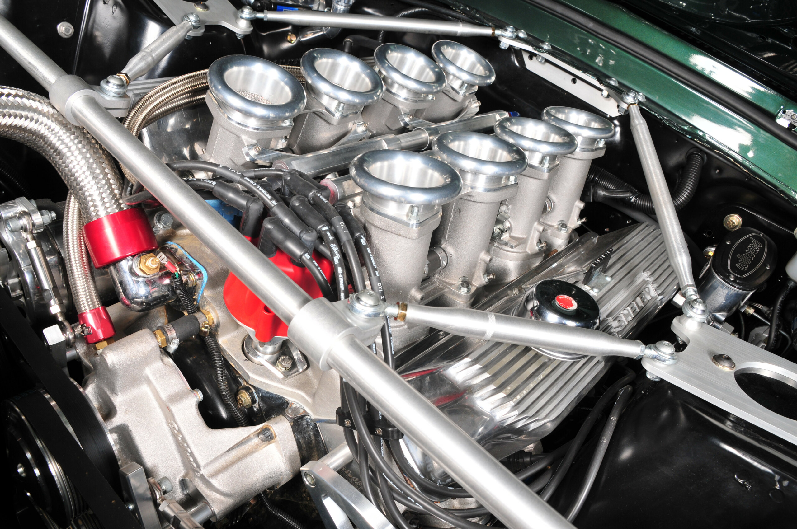
Mick, the owner of this sweet LHD ’67 Mustang fastback was looking to make his 427 FE-powered ride just that little bit more special and felt that this eight throttlebody EFI conversion from TWM/Borla fitted the bill perfectly — we most certainly agree.
The TWM system includes the four twin-throat throttlebodies, manifold, fuel rails, injectors, fuel pressure regulator, some fuel line fittings and the links and hardware needed to join the plates and synchronize their movements.
Getting the plates moving together is one of the most challenging aspects of multi-throttle set-ups. Mick also chose an Autronic SM4 ECU to control the whole set-up because of its high-end reputation.
While it has to be said that installing an Autronic isn’t as user-friendly as some other aftermarket EFI systems, the product is aimed at serious users rather than the home hobbyist sector of the market, and there are more suitable control systems for novice installers.
The Muscle Car Factory (MCF) invited us along to check out the installation of the TWM/Borla gear and Autronic management system on Mick’s mean green ’67.
THE CONVERSION, STEP-BY-STEP:
1a. The Total Control Products strut brace kit had to be removed to get the old equipment off and fit all the new gear. The billet hinges don’t allow for a wide bonnet opening so the bonnet also had to be removed for the job.
b. Once all the wires, lines and hoses were disconnected everything came off pretty much as you’d expect. The original ignition system was retained even though it’s less than optimal for the new set-up.
2. Although a manifold may fit straight out of the box, you’d be lucky — especially if the heads, deck or both have been machined. It’s more likely that the manifold faces and ends that seal the valley will need machining for correct fit.
The ports may also need a tickle to attain a good match. Port matching can be done at home but you’ll need the services of an engine machinist to accurately measure and mill the manifold.
3. It is possible to assemble the throttlebodies and the fuel rails onto the manifold prior to installation. However, for this installation it was simpler to bolt them up once the manifold was in place.
Here Leo (proprietor of the Muscle Car Factory) is dropping the throttlebodies in place. Be careful not to over-tighten the mounting nuts or you risk distorting the bases of the cast alloy throttlebodies.
4. Each injector rail is supplied in two halves that slip together — they seal via the visible O-ring. Installation is easiest if you attach the injectors to the rails and set them in place as you attach each pair of throttlebodies.
Injectors are supplied with the kit; when ordering, give TWM your engine and cam details so they can calculate your basic fuel requirements and supply suitably rated (flow rate) injectors.
5. Throttle actuation is via this cable-operated rotating cam disc in the centre of the manifold. It sits on a hollow block that’s a vacuum accumulator for the system.
A vacuum line from each throttlebody (red hoses) keeps it empty, while the central connection port (A) is the MAF sensor and brake booster attachment point. Throttle position sensor mounts to the rear of the left bank’s throttle shaft (not shown).
6a. TWM supplies cable and linkages to adapt the EFI to factory linkages. Unfortunately the Mustang’s bell-crank set-up fouled the rear throttlebodies — not uncommon — so it was replaced with Lokar’s Competitor Series throttle pedal assembly, complete with vertical offset mounting, which aligns the top lever with the existing hole.
b. It is important the cable moves freely to avoid binding, wear and possible failure.
7. Trim the outer cable (sheath) to length and slip it into the adjustable collar (A). Then feed the inner cable in, guiding it around the slot and through the small hole in the barrel-shaped clamping pin (B).
Use pliers to slightly tension the cable, then tighten the clamping pin. Fully depress the accelerator pedal and check the throttle plates are wide open. If they’re not, the accelerator pedal angle will need adjusting inside.
8. Low-pressure carby pump must be replaced with a high-pressure EFI unit — MCF replaced the entire tank. Mounted out of harm’s way, on a plate in front of the new alloy tank, is a lift pump (A) pushing through a line filter (B), which keeps the internal surge tank full.
Main pump (C) is fed from the surge tank and feeds the supply line and rails. A return line runs from the manifold-mounted regulator back to the tank.
9. A 3/8in line is the minimum for performance applications. Mick’s tough Mustang already sported an upgraded supply line but needed a return line.
When routing lines, keep them near underbody areas that provide shielding and use cushioned P-clamps to keep them secure and clear of moving components. Sections of hardline joined by rubber hose should be flared and clamped on either side.
10. While OEM manufacturers often mount the ECU in the engine bay, the aftermarket has found the interior’s cooler and drier environment to be preferable. Here, the Autronic SM4 was mounted to an out-of-the-way bracket beneath the front of the console.
It’s completely out of sight when the console is refitted, yet remains quite serviceable. Be sure to use a grommet when running the loom through the firewall.
11. The wiring diagram supplied by Autronic matches the colour coding of the wires, and the connections are fairly straightforward. The abundance of wires reflects the wide variety of things the unit can do — many functions will not be used, so many wires will remain unconnected.
Basic connections are injectors, ignition, power, earth and fuel pumps, plus throttle position, coolant temperature, MAP and oxygen sensors.
12. An oxygen sensor isn’t strictly necessary but it’s a good idea to fit one for each bank of cylinders. Apart from the usual advantages, their fitment allows Autronic’s ‘auto tune’ to be activated.
Once configured, this can be used to get a pretty decent map up and running. It’s no substitute for a comprehensive dyno tune but it will get you to the dyno. Note the coolant temp sensor at the back of the blue T-piece in Step 13.
13. The MSD dizzy and 6AL box were retained but modified — the advance weights and springs were removed and the advance plate locked at zero; the ECU now controls advance and retard.
A Hall effect sensor was added inside the dizzy so the ECU can calculate the internal position of the engine, allowing it to fire the appropriate injectors at the correct time, which in this application is in pairs across the engine.
14. For the system to operate properly, all of the throttle plates have to be synchronised. This is achieved by measuring the flow through each horn with a special air flow meter.
Basically, as soon as the engine can idle, the cylinder balance should be measured. Flow into each is measured at around 1000rpm and the variation between horns shouldn’t be more than about one graduation on the supplied meter.
15. Adjustment is complicated and time-consuming — it can take a couple of hours. Here you can see the idle stop screw (A) on the primary throttlebody (B) and the front/rear balance screw (C) linking the two together.
During synchronisation, the throttle linkage pull arms (Step 05) should be disconnected and the balance screws backed off completely. Start by adjusting the idle stop until the engine idles happily.
16a. Measure the flow through the front throat of the primary throttlebody (A), then adjust the balance screw (B) until the next throat (C) matches the first.
If the front and the rear throats don’t match the middle two, you’ll need to loosen the grub screw in the link-collar (D) and adjust their throttle shafts.
Further fine adjustments can be made using the bypass screws at the base of each throttlebody.
WRAP UP
During the synchronisation process, continually move from side to side and front to back. Once all throats are equal, you can then set final idle — again use the flow meter to ensure one side is not pulling more than the other.
In an angry engine like this, there’s no doubt that an EFI system offers more control over the tune than a carburettor. In fact, even with a basic pre-dyno tune this car idles much more smoothly. Mick misses the spitting, coughing and bucking but really that was a sign that the old carburetted system wasn’t working very well.
Fitting the manifold and the throttle hardware is fairly easy and well within the abilities of the general enthusiast. However, the engine management side of things is a different matter, with many opportunities for mistakes. Though it’s brilliant, the Autronic is particularly difficult for an amateur to fit.
Still, it can be done with care and perseverance and it has some very nice features, such as the auto tune along with the Throttle Limit Learning routine that simplifies matching the TWM TPS to the Autronic ECU.
While it certainly looks bitchin’ uncovered, driving without the TWM-supplied air cleaner isn’t wise.


Comments