Engines, rolling stock, chrome and paint are all glamour elements of street machining. On the other hand, your streeter’s electrical system and associated components tend to be somewhat neglected. Without a properly functioning electrical system the rest is next to useless. Therefore understanding the principles behind its operation is vital to keeping any streeter running.
People tend to be scared of things they don’t understand and this is especially true when it comes to auto electrics. So this month we’ll try to demystify some of the theory while next month we’ll look at some practical applications.
First published in the January 2006 issue of Street Machine
CURRENT, VOLTAGE, RESISTANCE
These three fundamental terms are your friends when dealing with electricity. Their relationships are described via Ohm’s law (see bottom of page). While most people comprehend resistance, the same cannot be said for current and voltage. A good analogy is water, where voltage is the equivalent of water pressure and current is water volume. Fully opening a household tap and busting open the water main that feeds your whole suburb will result in vastly different amounts of water pouring out even though they are at the same pressure. The reason is the household tap has less flow capacity (current flow) than the water main. Now go in the opposite direction and hook up a high-pressure water blaster to the same household tap. The water pressure (voltage) coming out of the blaster’s nozzle is dramatically higher than the pressure coming out of the tap, however the volume of water (current) is significantly reduced. Consider current as the volume of electricity and voltage as the pressure at which it’s being pushed.
WHAT’S HAPPENING
People talk about connecting power, but what they really mean is current. Current flow occurs when loosely bound electrons jump from one atom to the next. Electrons try to distribute themselves evenly throughout a conductor, therefore if there are more at one end than the other, their desire will be to flow from the point of greatest concentration toward the point of lowest concentration until there’s an even spread. The excess of electrons at one point is known as potential difference, or voltage. The greater the number of electrons piled up, the higher the voltage (potential difference).
CAR ELECTRICITY
There are two forms of current: AC (alternating current) and DC (direct current). Your home uses AC in which the direction of current flow changes direction 50 times a second. Cars use DC, which flows in one direction only — out of the battery’s positive terminal, through the device and back to the negative. Without a completed, unbroken circuit there is no current flow and the device will stop operating. Hooking a test light between a battery’s positive and negative terminals is a very simple circuit that’s easy to visualise.
THE BATTERY
Effectively, a car battery has a big pile of electrons at one terminal and deficiency at the other. The battery’s job is to start the car and power everything when the engine is not running. Once the engine’s running the battery becomes nothing but a big filter and reservoir as all the car’s power needs are supplied by the alternator.
ELECTROMAGNETS
Every school kid has wrapped insulated copper wire around a nail and run a current through it, turning the nail into a magnet — an electromagnet to be exact. Talking magnets, it’s commonly known that if you bring two like poles together they repel, while opposite poles attract. These three principles are used extensively in automotive electrical systems. In an electric motor, electricity is passed through the two separate windings to create two electromagnets that are positioned so that their like poles are close to each other (so they will repel). The outer electromagnetic field is fixed (to the case of the motor), while the central electromagnetic field is allowed to move (rotating on the central shaft). Hence magnetic repulsion makes the armature (centre section) spin. Some motors, like those used for wipers and some modern starter motors, use permanent magnets instead of an electromagnet to form the outer field. These are known as per-mag motors.
CHARGE IT UP
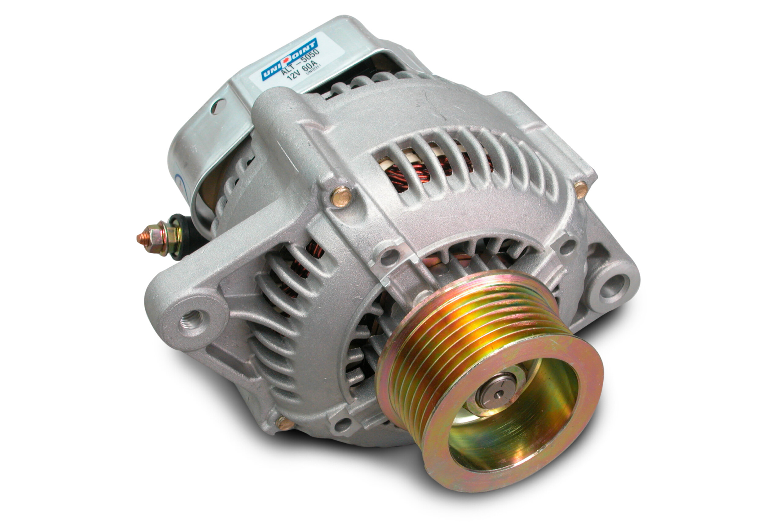
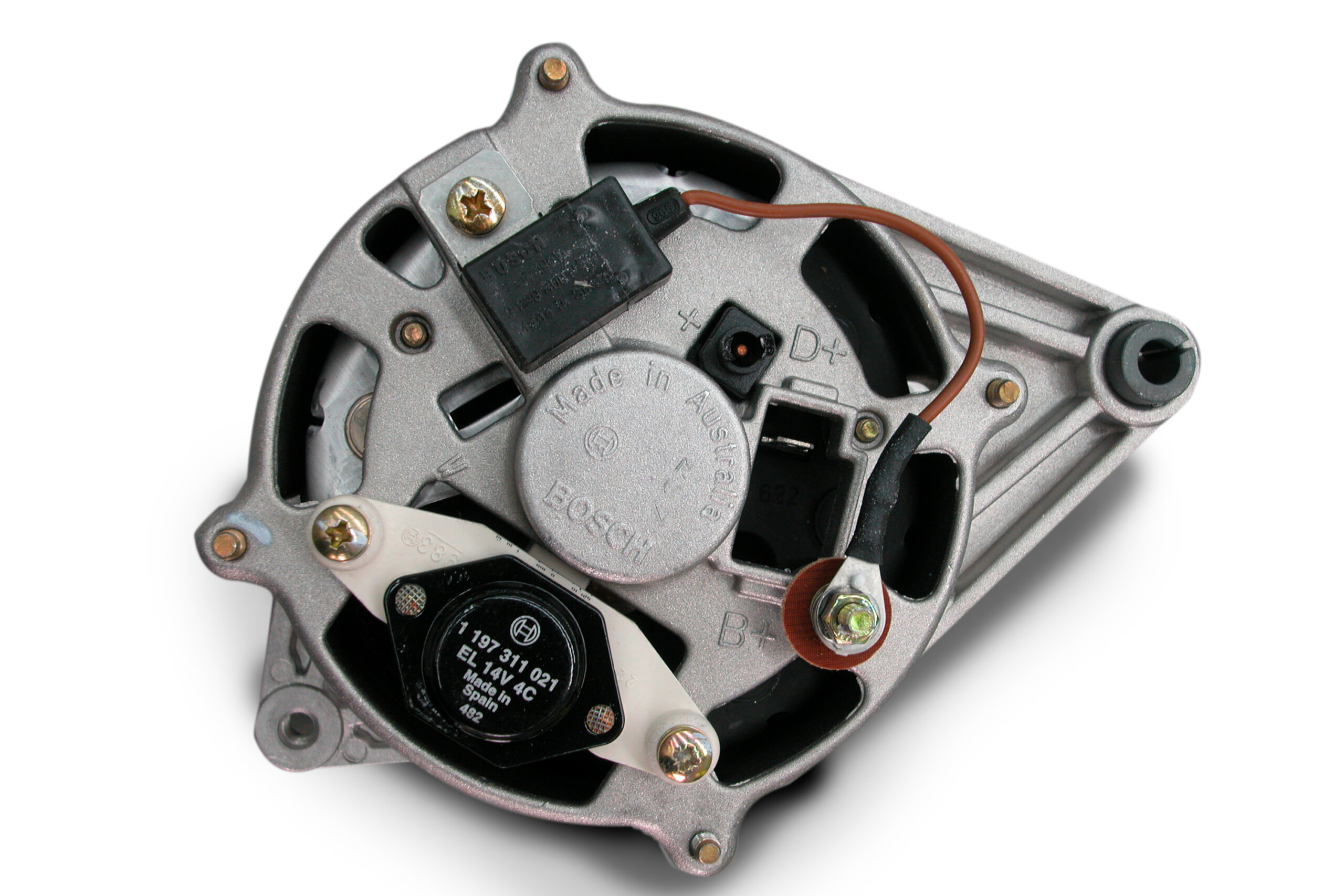
Whevever current flows through a conductor, a magnetic field forms around that conductor; this is why the nail becomes magnetic. The reverse is also true: when you pass a magnetic field across (not along) a conductor, a voltage will be induced in that conductor. Although their exact operations are slightly different, generators and alternators both exploit this principle. Here the car’s engine spins an electromagnet inside a set of windings. This action induces a voltage into those windings. Due to their superior efficiency, alternators made generators redundant. Fifty years ago, a 35A generator-based charging system was more than adequate to run a car. Modern cars, however, have a vast array of electrical devices requiring the fitment of 80, 120 and even 180A alternators.
NOMINAL VOLTAGE
The 12V rating of your car’s electrical system is actually a nominal rating. In the real world voltages vary between 10 and 14V. When cranking, current-hungry starter motors will pull the system voltage as low as 10.5V. Alternator output starts low and ramps up as revs increase. To enable it to supply sufficient power and current at low engine speeds, alternators are designed to pump out up to 20V and are then regulated down to a constant 14.0 to 14.4V. Keeping this voltage at the battery terminals will replenish the battery after starting, and supply your streeter’s electrical demands.
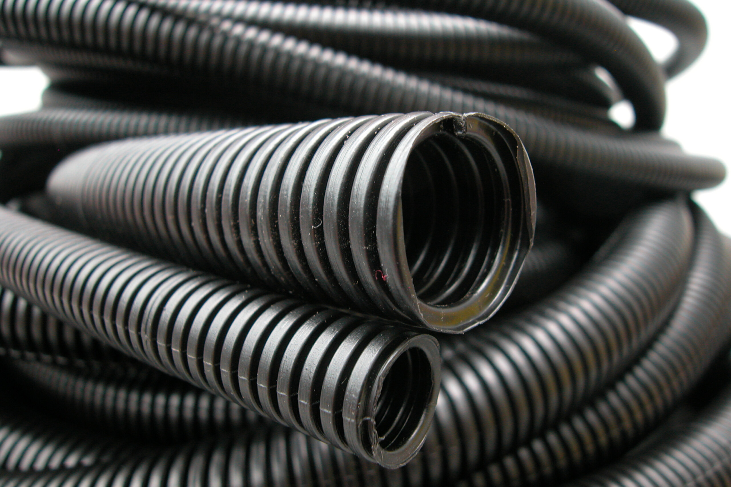
VOLTAGE DROP
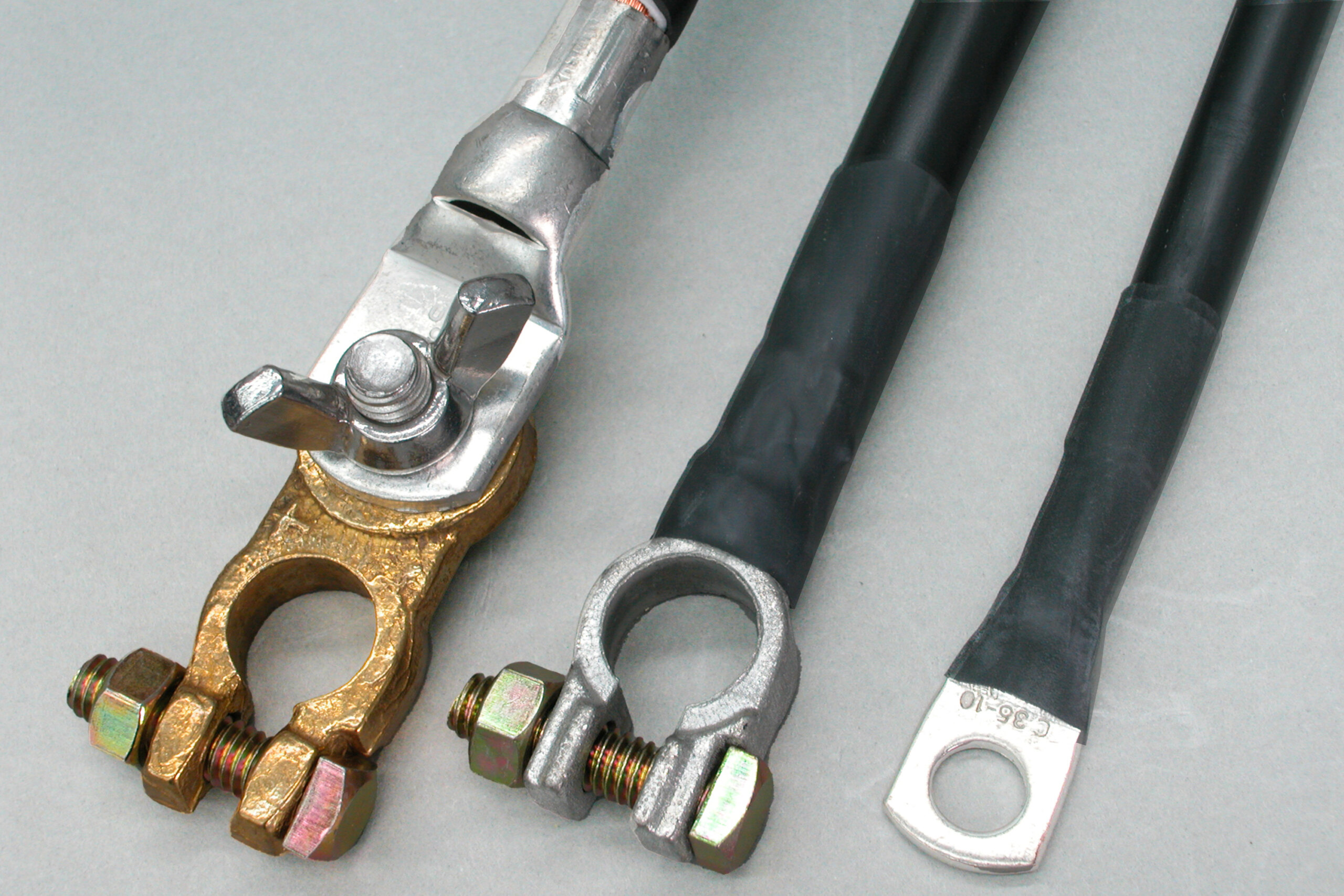
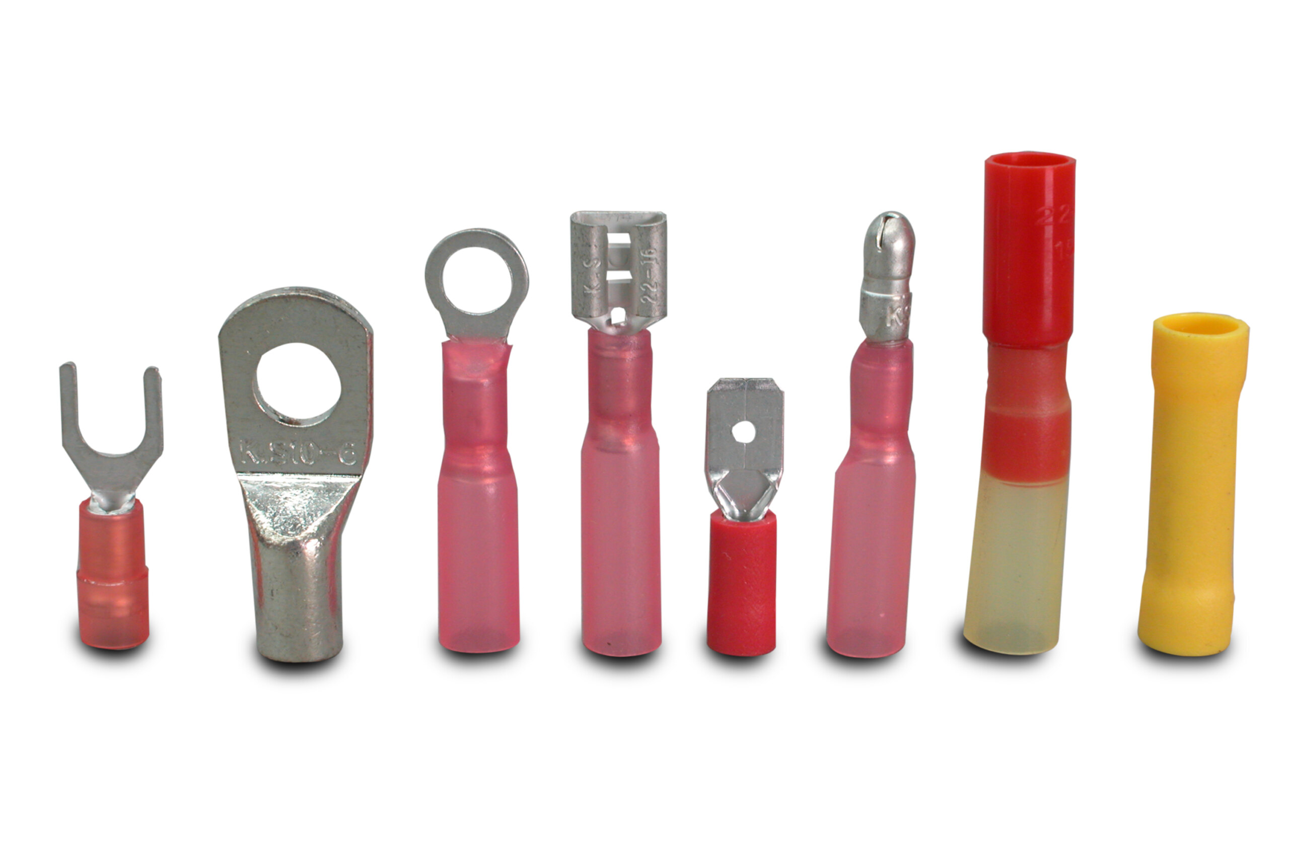
Whenever current flows through a conductor you get voltage drop. Minimising this voltage drop is paramount in creating an effective electrical system. This is done by using correctly rated fuses and wire, and good, clean termination. The larger the cross-sectional area of a conductor (wire), the lower its internal resistance and the lower the voltage drop it will experience. This is why big, current-hungry devices require big, heavy cables. Use too small a cable and it will heat up, resistance will rise dramatically and whatever it’s feeding will receive insufficient voltage.
EARTHING
Earlier we stated that DC current requires a complete circuit to operate, yet in the automotive arena most electrical components have only one wire leading to them. This is because the return path to the battery negative (the earth) is made through the metal car body which saves on wiring. Additionally, its cross sectional area is quite significant so it offers an extremely low resistance return path. Well-known race tuner and pedal man Mike Trahar, from Mike’s Dyno Tuning, is an auto electrician by trade and says that poor earth connections are one of the biggest causes of electrical faults in the automotive field.
“It’s common for people to earth a relay by looping a wire around and connecting it between the relay mount and the body. But if they haven’t cleaned the paint off the body at that point properly they often fail to get a good earth contact,” he says.
Engine to body or chassis earth is another example, as the engine and gearbox assembly is typically insulated through its rubber mounts. Always earth directly to clean metal — a good rule of thumb is to use the same gauge wire to earth a device as used to feed it.
FUSES
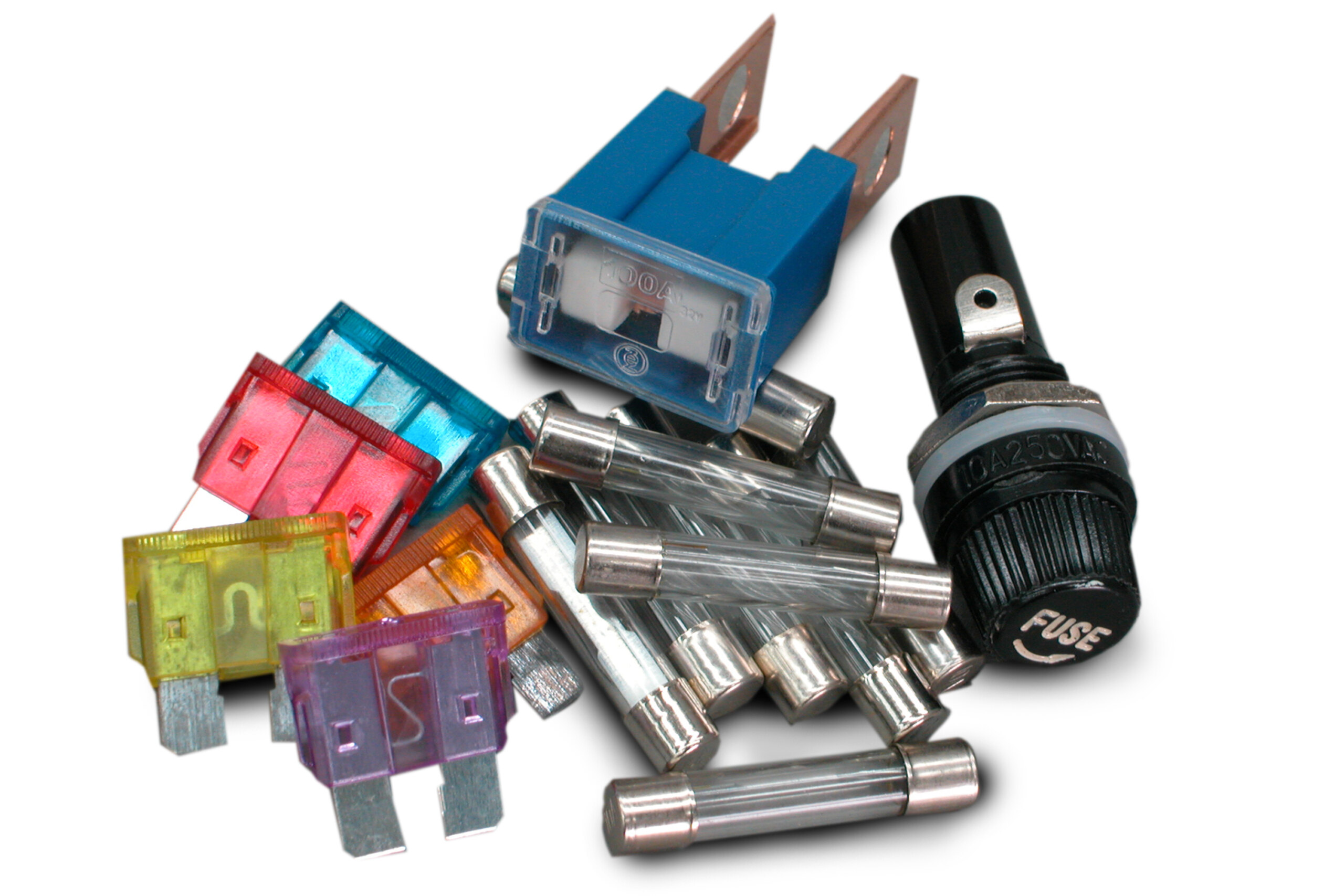
Contrary to popular belief, fuses are designed to protect the wire not the device at the end of the wire. A device or circuit will only draw the current it needs. When something goes wrong within the device its current draw can drastically increase, well above what the wire feeding it is capable of handling. Without a fuse, the wiring would try to flow the excessive current, possibly becoming red hot and melting off the insulation — burning out the wiring. If this happens, the wiring has to be replaced, usually along with any wiring running near to it. This is why you should never fix a blown fuse by slotting in a larger one — especially not one covered in cigarette foil. Every circuit that carries current must be fused, otherwise fire will most probably ensue in the event of a malfunction.
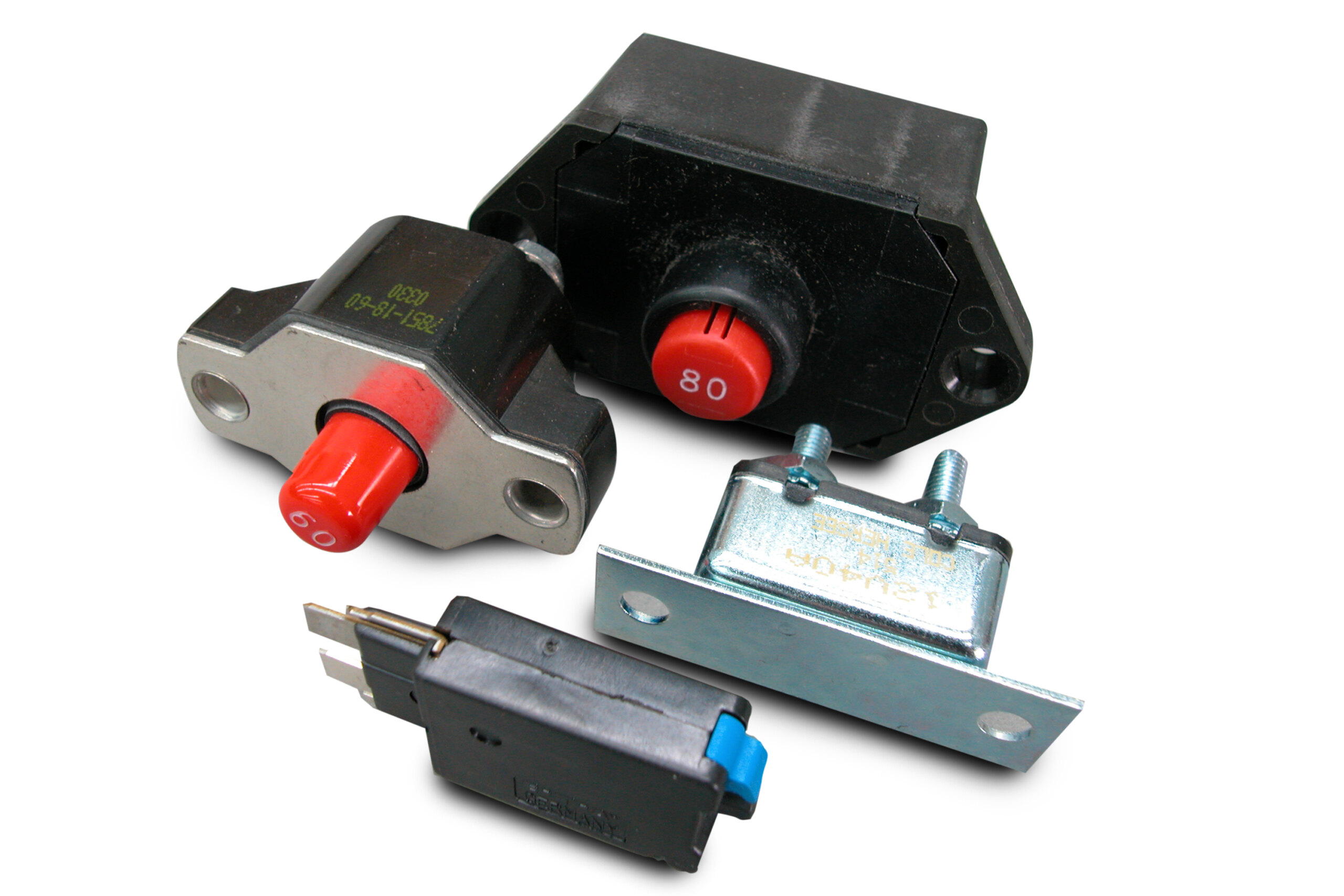
CIRCUIT BREAKER
Circuit breakers and fuses act in much the same way except that once a fuse blows it must be replaced, while a circuit breaker can be reset, either automatically or manually. Imagine rounding a fast mountain bend at speed and the headlights suddenly shut off and stay off due to a fault in the circuit. With a circuit breaker, shutting the circuit down takes longer and it can then cycle on and off. Fuses are finite.
SHORT CIRCUIT
Each component connected to the battery has internal resistance. It’s this internal resistance that limits the amount of current flowing through it and the wiring connecting it to the battery. If the component load is eliminated from the circuit (ie: when the wire feeding it touches earth or the device fails internally) there’s nothing to limit current flow. The circuit will then try to flow the maximum available current that the battery can supply — up to 1000A — this is known as a short circuit.
PEAK VS CONTINUOUS
Some circuits will experience high current draw for short durations. Electric motors, for example, draw up to 50 per cent more current on start up than it takes to maintain their operation. Also, when a motor stalls under load, as when a power window reaches the end of its travel and the switch isn’t released, current flow increases enormously as the motor acts somewhat like a short circuit. Allowance must be made for this extra current draw when selecting wiring along with size and type of fusing.
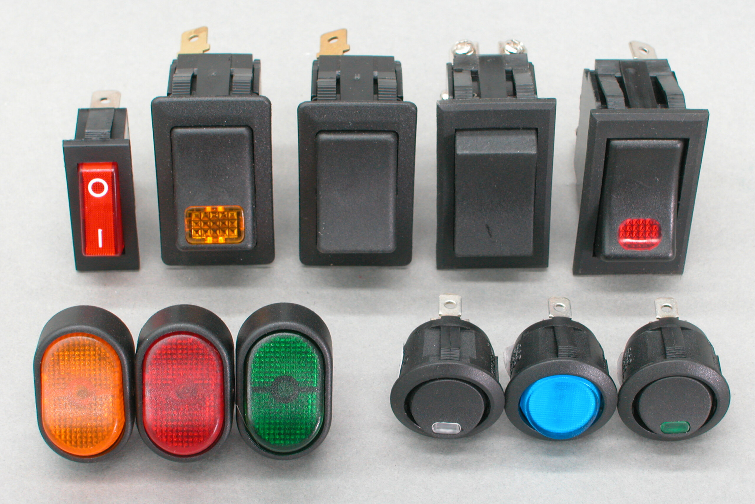
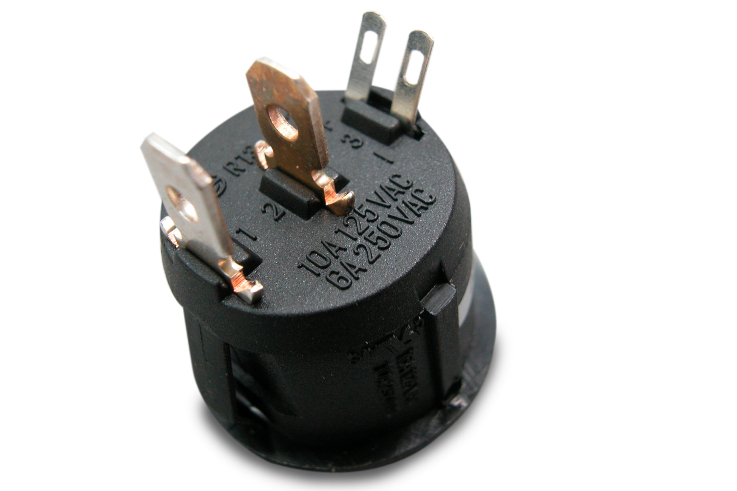
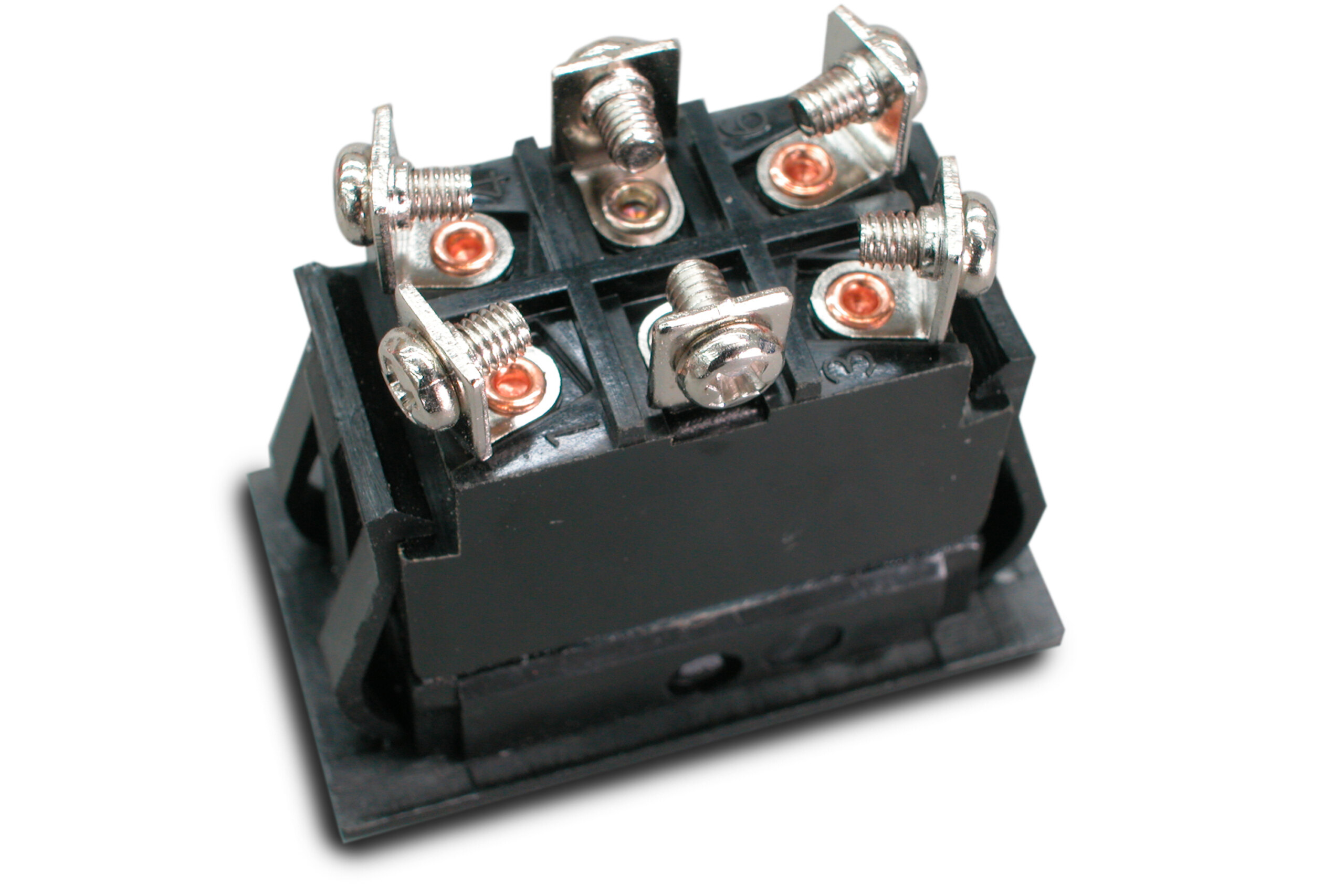
SWITCHES
In simple terms, a switch does nothing more than break the continuity of the circuit. Going back to our previous scenario of the test light across the battery terminals, simply removing one end of the test light from either terminal does exactly the same job as a switch, nothing more, nothing less. Flicking the switch is just like physically cutting the wire — a brake-light switch or two-terminal toggle switch is about as simple as things get. Where switches get complicated is when one physical action operates multiple sets of contacts inside the switch. But when it’s all said and done, every set of contacts can only ever be open or closed.
RELAYS
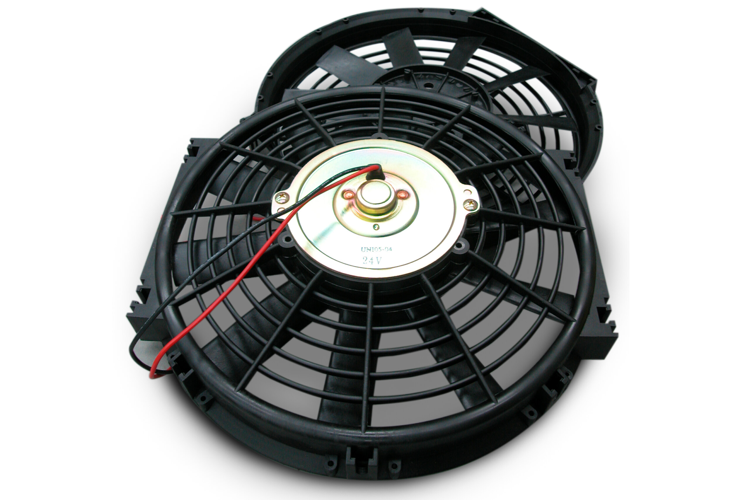
Big current flow requires a big, beefy switch which is not always practical. Relays are used to get around this problem. Relays are simple devices that use a little current to switch a big current. Inside a relay is an electromagnet with many turns of fine wire which draws very little current (hence it can be operated by a lightweight switch). When activated, the strong induced magnetic field pulls a set of heavy-duty contacts together which completes the circuit for the heavy current device — usually headlights, fan motors, demisters, fuel pumps, horn or the like.
Relays are used to reduce the number of connections in the main current path (each of which is a source of potential problems and voltage drop). Additionally, resistance to current flow increases with the length of a conductor, so relays can be used to shorten the main current supply path between the battery and current-hungry components.
SOLENOIDS
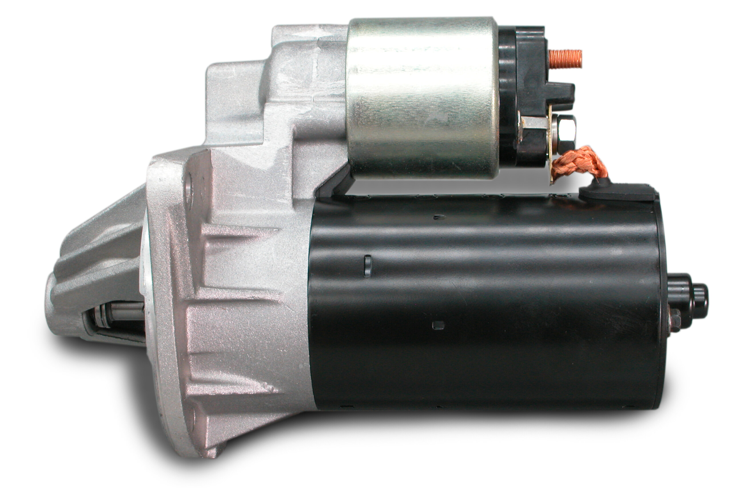
Solenoids feature very strong electromagnets which, when energised, retract a central (iron) plunger. The boot release is a common use for solenoids. They can also be used to pull the door mechanism if you shave the door handles. In a starter motor the solenoid does two jobs: the retracting action is used to push the drive pinion forward so that it meshes with the ring gear. It also contains a set of very heavy-duty contacts inside the end-cap that operate when the plunger goes all the way in. Once coupled, they supply the huge current (300-1000A) to the starter motor so that it can crank the engine.
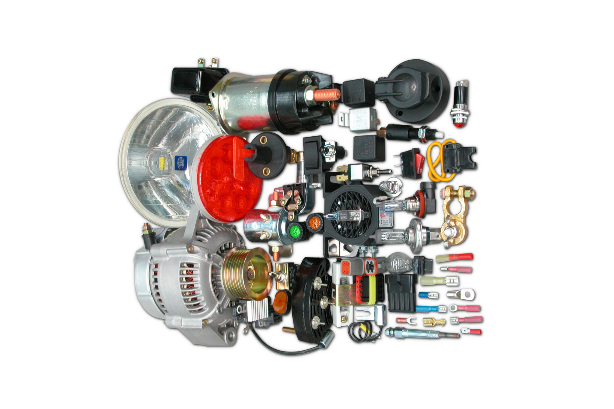
So that’s the basics of circuits and auto-electrical matters in general. Mike from Mike’s Dyno Tuning helped us with practical tips in this article, while Australia-wide electrical supplier Ashdown lent us all the components shown. It has just about everything you’d want.
OHM’S LAW
Knowing voltage, resistance and current flow is vital when piecing together your car’s electrical system. Using Ohm’s law, if you know two values you can calculate the third. And don’t worry if you’re not an algebra whiz, Ohm’s law is a very easy equation to work with.
The basic law is V=IR, where V = voltage, I = current and R = resistance. See the accompanying side bar for all the possible permutations. With a bit of manipulation Ohm’s law can also be used to calculate power. That is P=VI, where P = power. Just like with V=IR you can swap things around and you can also substitute IR in for V or V/R in for I.

Knowing any two values allows you to calculate a third, helping you to correctly select maximum power loads for circuits, appropriate wire gauges and fuse sizes. Let’s look at two practical applications. Suppose you wanted to hook up a pair of 150W driving lights. You know the voltage will be between 12 to 14 volts (split the difference and say 13V) and you know the power rating (150W), but you need to calculate how much current they will draw (I). Slotting the two known numbers into I=P/V, we get 150 divided by 13, which equals 11.5amps. Therefore you need to install two circuits (there are two 150W driving lights) capable of handling 11.5A each or one circuit capable of handling 23A (2×11.5).
Now say you have wire (or a fuse) rated at 15A and you want to know what you can hook up to it. We know voltage and maximum current flow and need to calculate power. Using P=VI we get 13 multiplied by 15 which equals 195W — therefore the combined ratings of all the devices hooked up to this wire or fuse must add up to less than 195W.

RELAY HOOK UP
Although pin layout varies, the relay numbering system is virtually universal. Terminals 85 and 86 are either end of the electromagnet winding — connecting 12V to terminal 85 and earthing terminal 86 will energise the electromagnet. Note you can switch either the positive or the negative side, it makes no difference. Terminals 30 and 87 carry the load — 30 goes to the main battery supply (12V), while 87 goes to the device. Many relays have two 87 terminals; these are simply joined together internally. One variation is the change-over relay where one terminal is marked 87A (not shown). At rest, terminal 87A and terminal 30 are connected. When activated, terminal 87A is disconnected and terminal 30 becomes connected to terminal 87. This type of relay is ideal for operating things like power windows where you need to change the direction of current through the motor to change its direction of operation.

Comments