Leaf springs were fine back in the day but now you have better options
DITCHING your streeter’s archaic leaf spring suspension system for a multi-link set-up brings many advantages. As well the lower unsprung weight giving improved suspension response, handling and braking, you also get simpler height adjustment, and reduced axle steer during suspension travel — especially when cornering — less differential rotation (axle wind-up) under hard acceleration and better power handling.
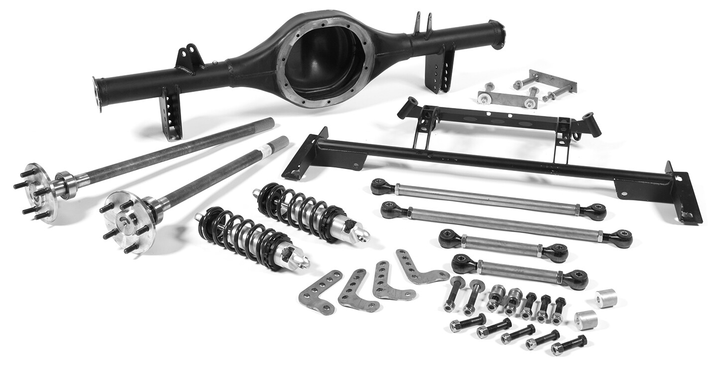 With this in mind, McDonald Brothers Racing has developed a range of universal and model-specific four-link rear-end kits — available either in parallel or triangulated (angled top arm) designs. Its kits can be purchased in various forms, from a simple bar and bracket set, right up to ready-to-run rear diff and suspension assemblies complete with centre, axles and brakes.
The range of kits can be broken down into three broad categories: specific fit bolt-in; universal weld-in; and the complete replacement rear-clip, which incorporates new pre-formed (rolled) chassis rails.
Two of McDonald’s other additions are a bolt-in kit that converts IRS-equipped VT-VZ Commodores to a parallel four-link set-up with a Panhard bar, and this bolt-in triangulated four-link kit for early Mustangs.
It’s an incredibly easy set-up to install, as we learned when we watched as Sefton Smash installed one into a customer’s partially finished 1965 fastback.
STEP-BY-STEP
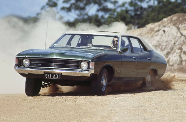
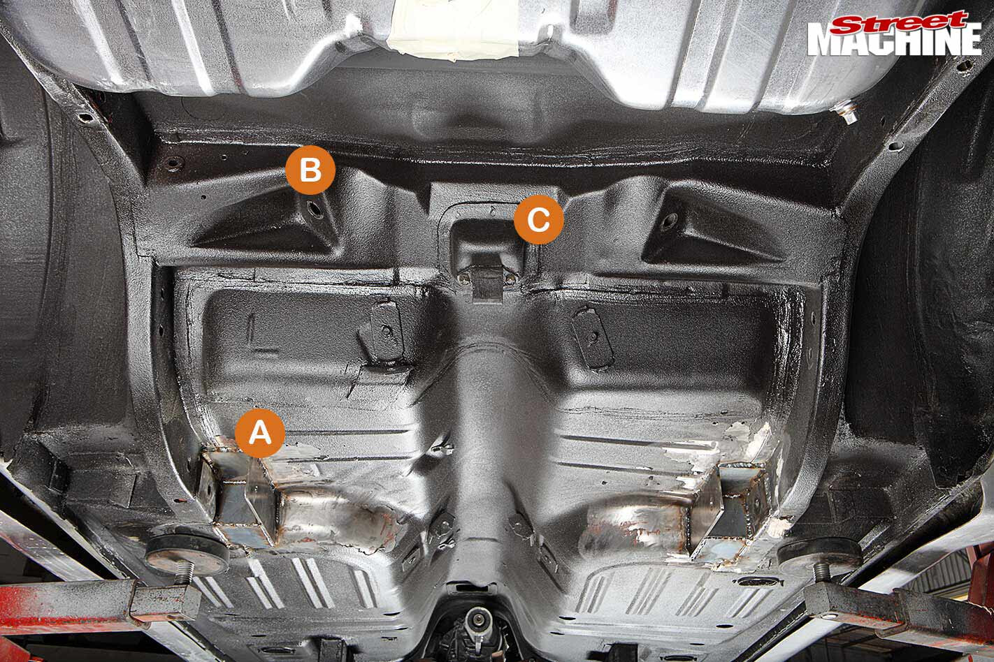 1. Owners of pre-XE Falcons and pre-1974 Mustangs will recognise this layout. While slightly tweaked over the years, this floor and chassis design served Ford well from 1965 right through to the end of the XD’s run in 1982. The key points are the front leaf springs mounts (A), shock mounts (B) and pinion snubber mount (C). McDonald’s uses these original mounting locations for its bolt-in four-link kit.
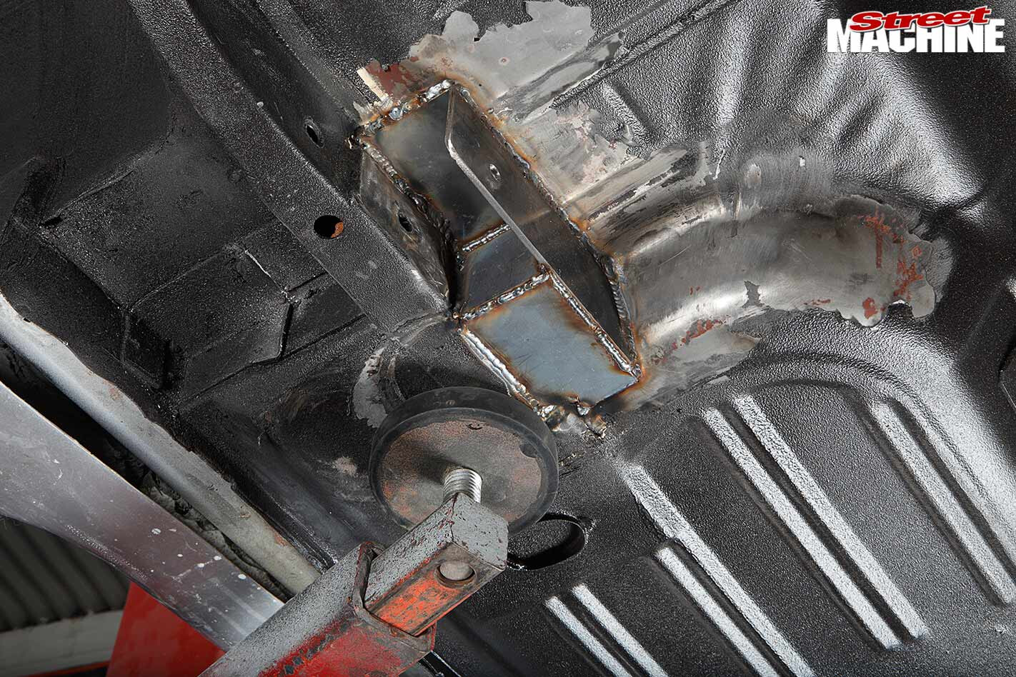 2. Prior to installation, this Mustang had been mini-tubbed — the inner wheel wells had been widened out to sit flush with the chassis rails. To take advantage of the extra room, it’s then customary on leaf-sprung Falcons and Mustangs to move the spring mounts from the outside of the rail to the inside, as shown here. The McDonalds kit can be ordered to suit either factory or relocated spring mounts.
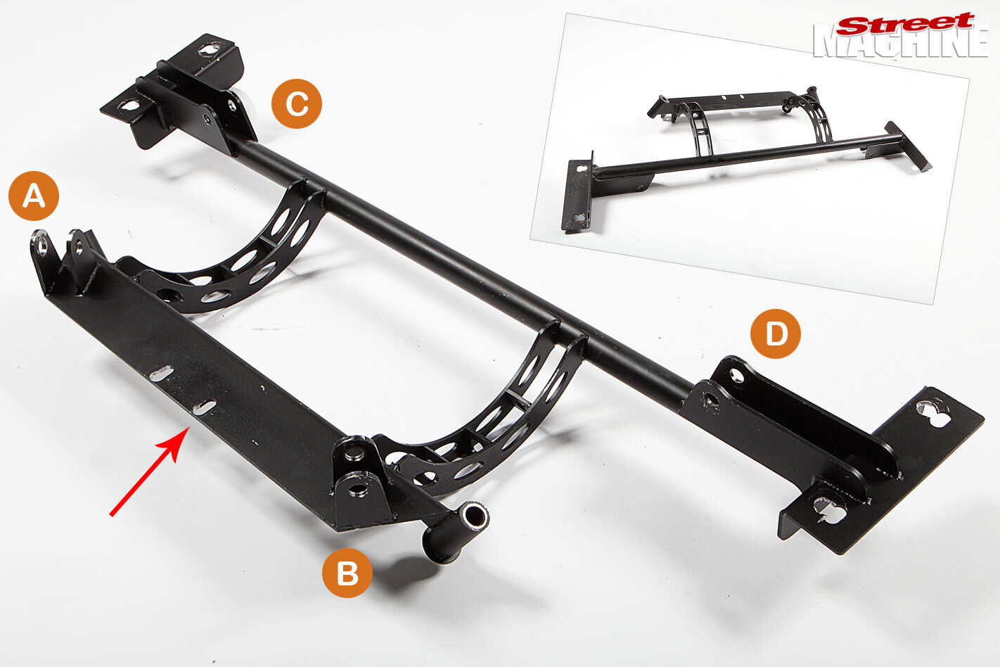 3. This sturdy bolt-in cradle is the heart of the system. It provides top arm (A&B) and coil-over (C&D) mounts. Triangulated four-link designs are often easier to build into street cars than parallel designs as the angled top arms make them more compact (no need to modify the rear floor or seat area), while simultaneously providing lateral differential location (no need to add a Panhard bar or Watts linkage). See more below.
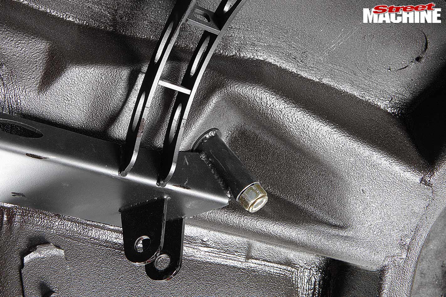 4. Before installing the cradle, unbolt and remove the pinion snubber. Then simply hold the cradle up in place, insert the two large bolts into the original shock mount holes (be sure to fit the heavy-gauge washers on the inside) and lightly nip up the Nyloc nuts. Then refit the two snubber bolts through the mounting plate (see arrow in Step 03). The cradle should now be held securely in place.
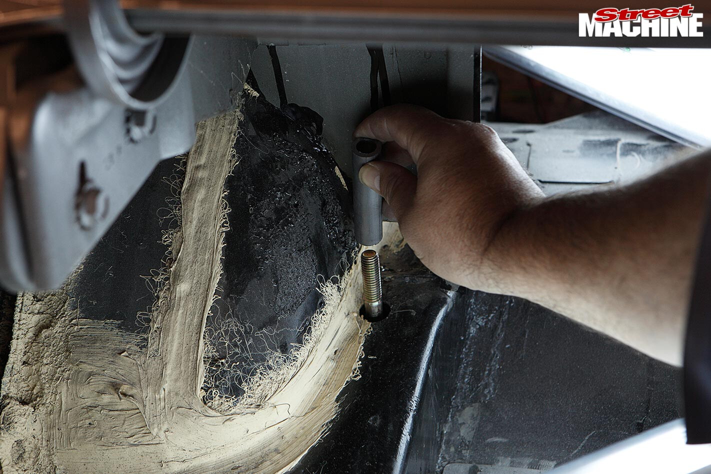 5. At this point, ensure the two end-plates (see arrow in Step 06) are sitting flush along the bottom edge and inner side of the chassis rail. Using the holes in the end-plates as a guide, drill a half-inch hole up through the chassis rail into the boot. Once through, drill a 9/16in hole through the top panel only — a step drill works well. Insert the crush tubes and drop on the load-spreader plates as shown in Step 06.
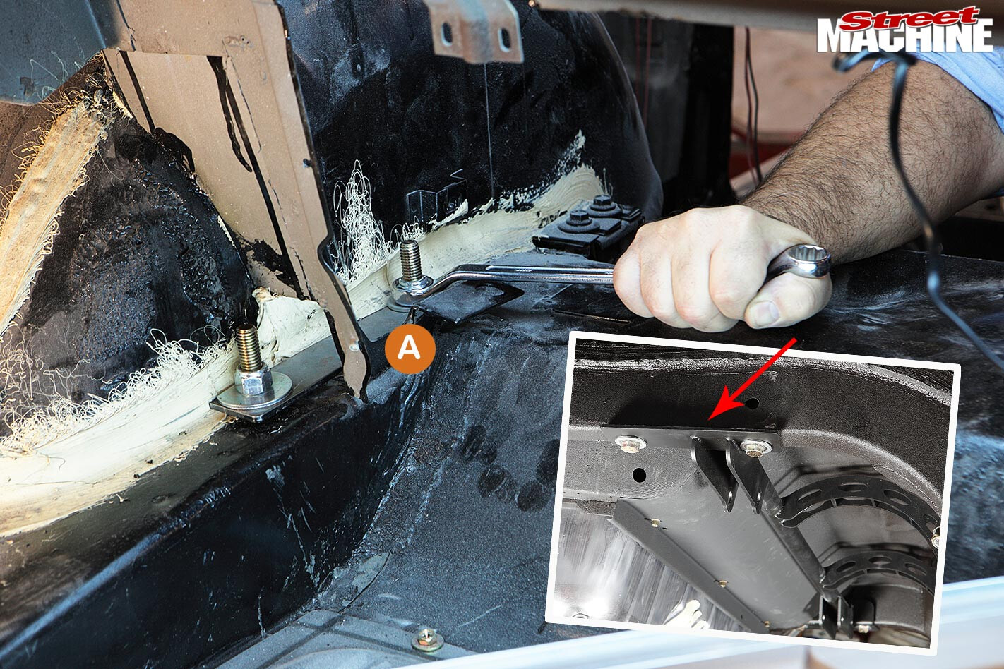 6. The load spreader plate is the thick, flat bar (A) that runs between the two bolts and distributes the stress. With it in place, drop on the two thick washers and torque up the Nyloc nuts. Once the four outside bolts are torqued, go back and properly torque the two shock mount and snubber mount bolts. This is all that’s involved in installing the cradle; it’s really very straightforward.
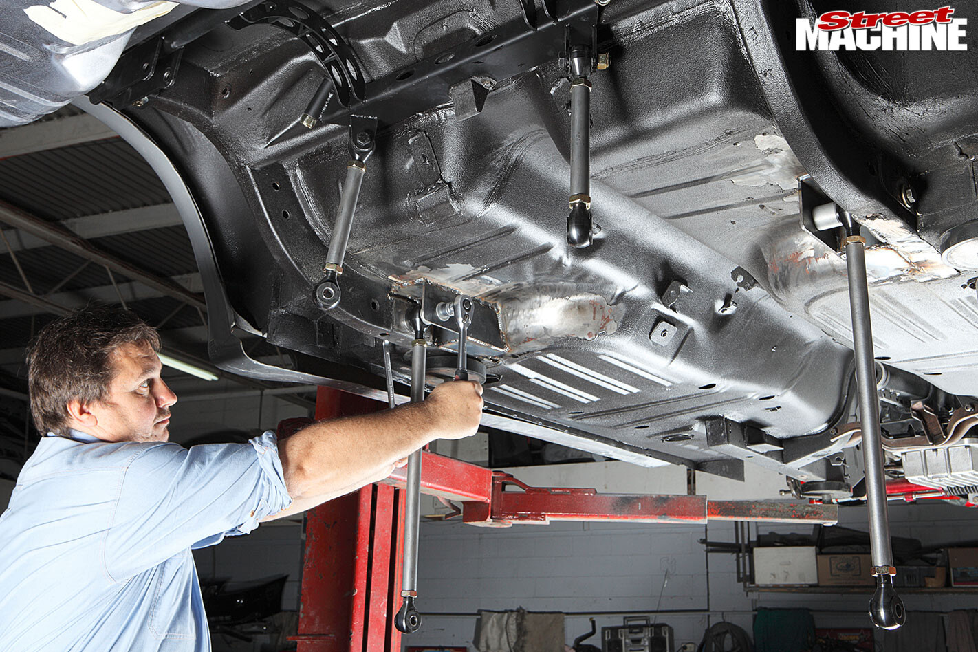 7. The locating links (bars) are constructed from 25mm diameter, thick-wall (3.96mm) tubing, internally threaded at either end. While ensuring the two shorter bars and the two longer bars remain equal in length, adjust them so that about 10mm of thread protrudes past the lock nuts. Nip the bolts up just enough so that the links can hold themselves in place when rotated into position, as this eases installation.
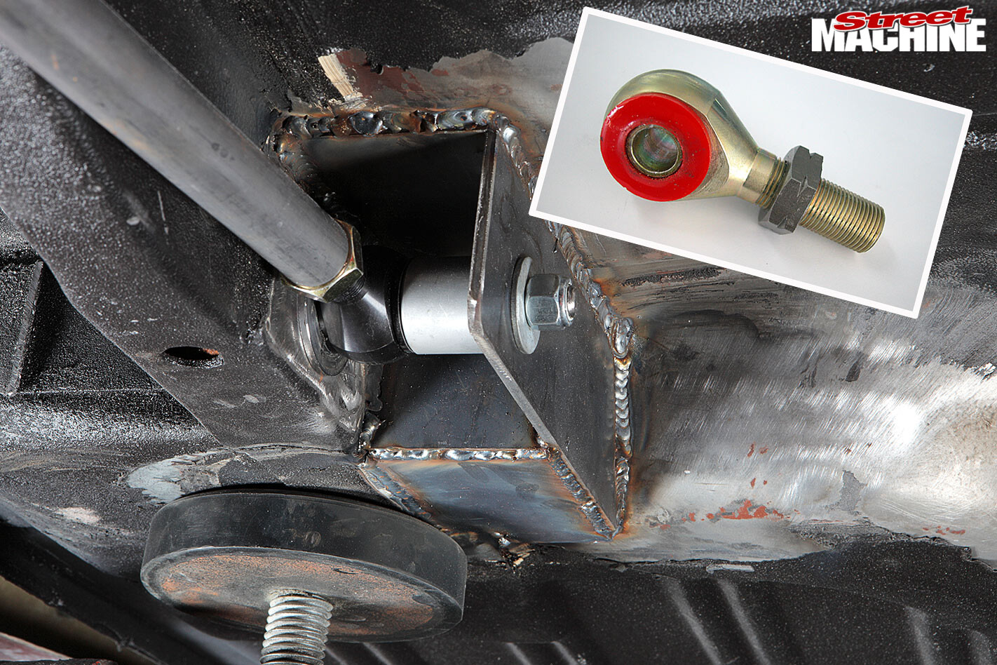 8. Using traditional spherical rod ends (also known as heim or rose joints) results in an overly harsh ride in street applications. These unique clevis ends, developed by McDonalds, are ultra-strong yet their urethane inserts provide a more supple ride and up to 27 degrees of angular deflection. Note the machined alloy spacer designed to take up the gap normally occupied by the 2.5in-wide leaf spring.
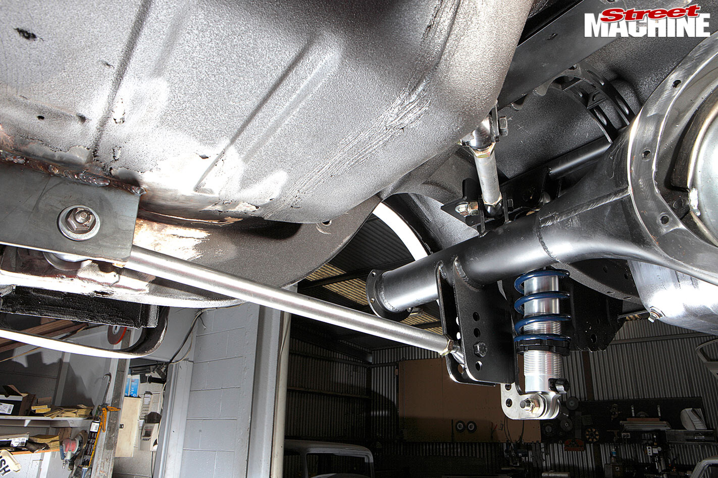
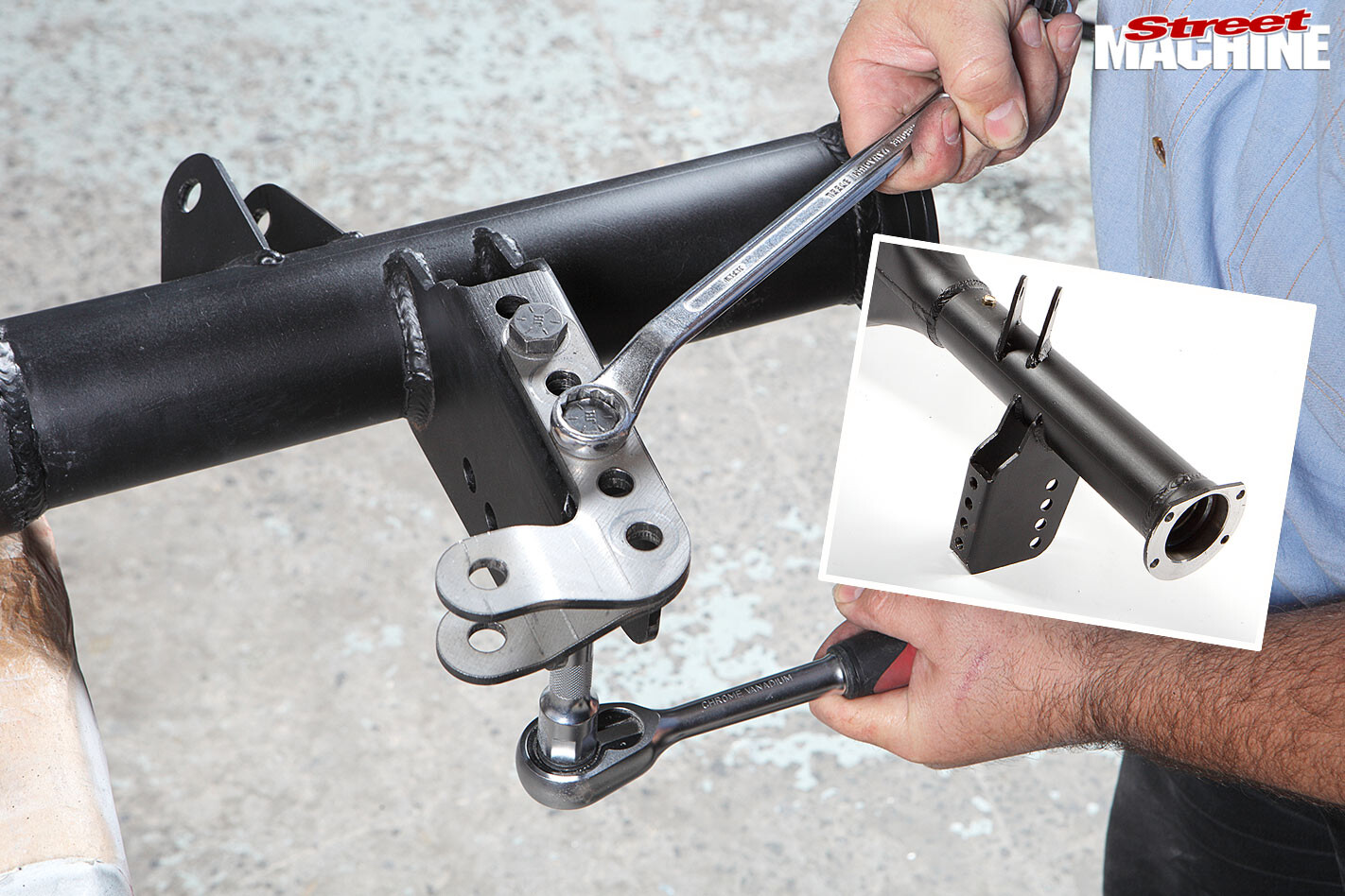 9. A significant amount of height adjustability has been built into the kit. The four holes on the diff bracket in combination with the five holes in the shocker mount provide more than 75mm of height adjustment. Two bolts must always be used when attaching shocker mounting brackets to the differential housing. The position shown results a ride height approximately three inches lower than standard.
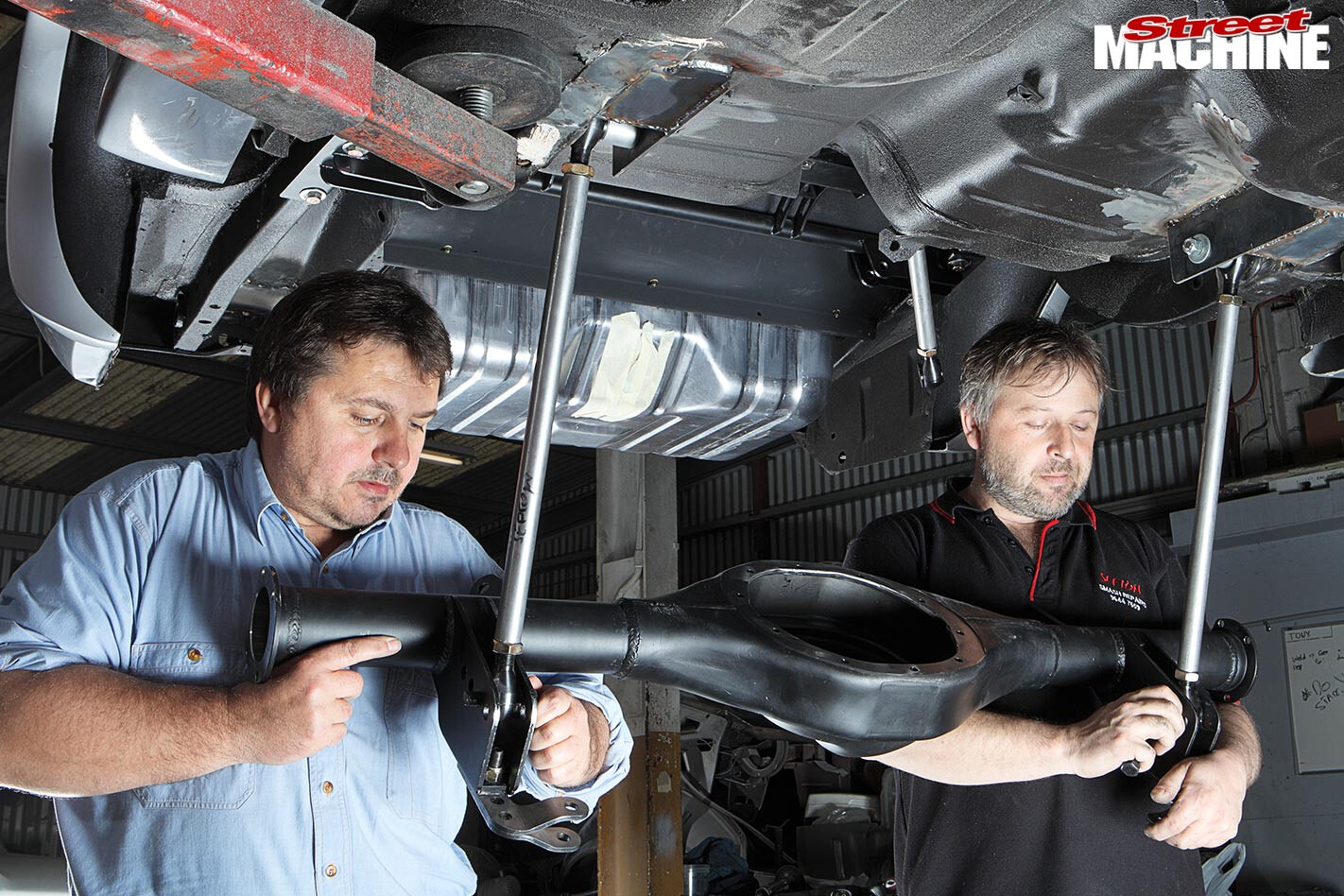 10. While the differential can be installed fully assembled, it’s significantly lighter and easier to manage without the centre, axles and brakes fitted up — so we fitted the housing bare. The easiest method is to attach the two lower links, then swing the housing up and slot in the angled top arms. For the sake of neatness, we positioned all the bolt heads on the outside, with the threads facing inwards.
 11. Ideally, you want the lower link as near to parallel with the ground as possible at ride height. That turned out to be the second hole from the bottom in this installation. Again, don’t fully tighten the fasteners, as it hinders the set-up and adjustment process. In fact, to eliminate all preload in the pivots, final tightening should only be completed with the car sitting on its suspension at the desired ride height.
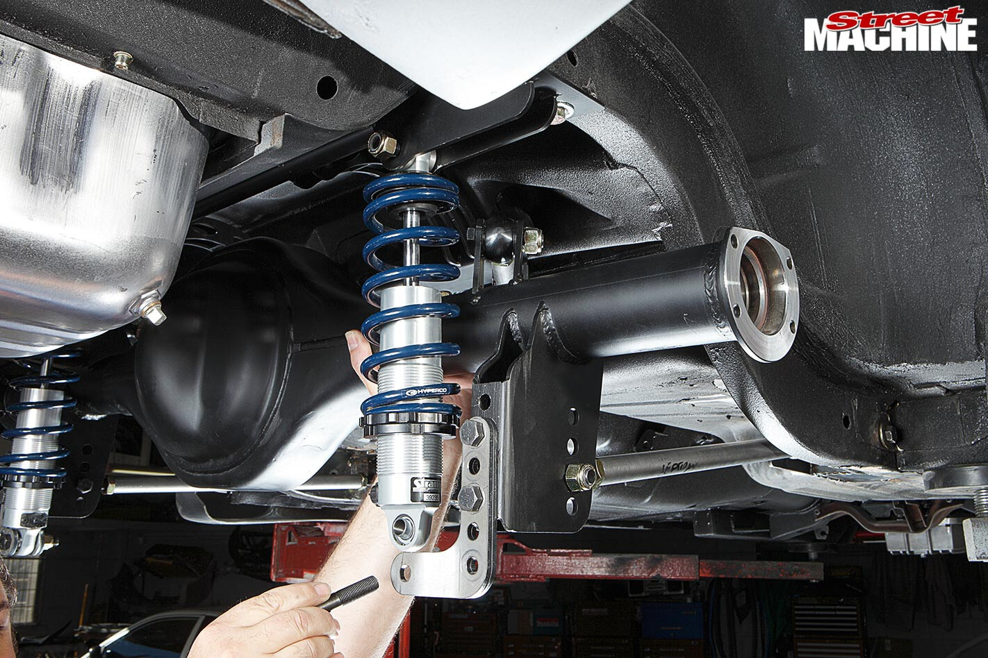 12. Adjust the two locking collars until the spring is captive (that is, the spring bears against the top and bottom plates) then install the coil-over. It’s important the springs remain captive at full droop. When adjusting final ride height, you can move the collars up to fine-tune the stance a little higher but if you need to come down, you’ll need to move the shock mounting bracket (arrow) to a lower position.
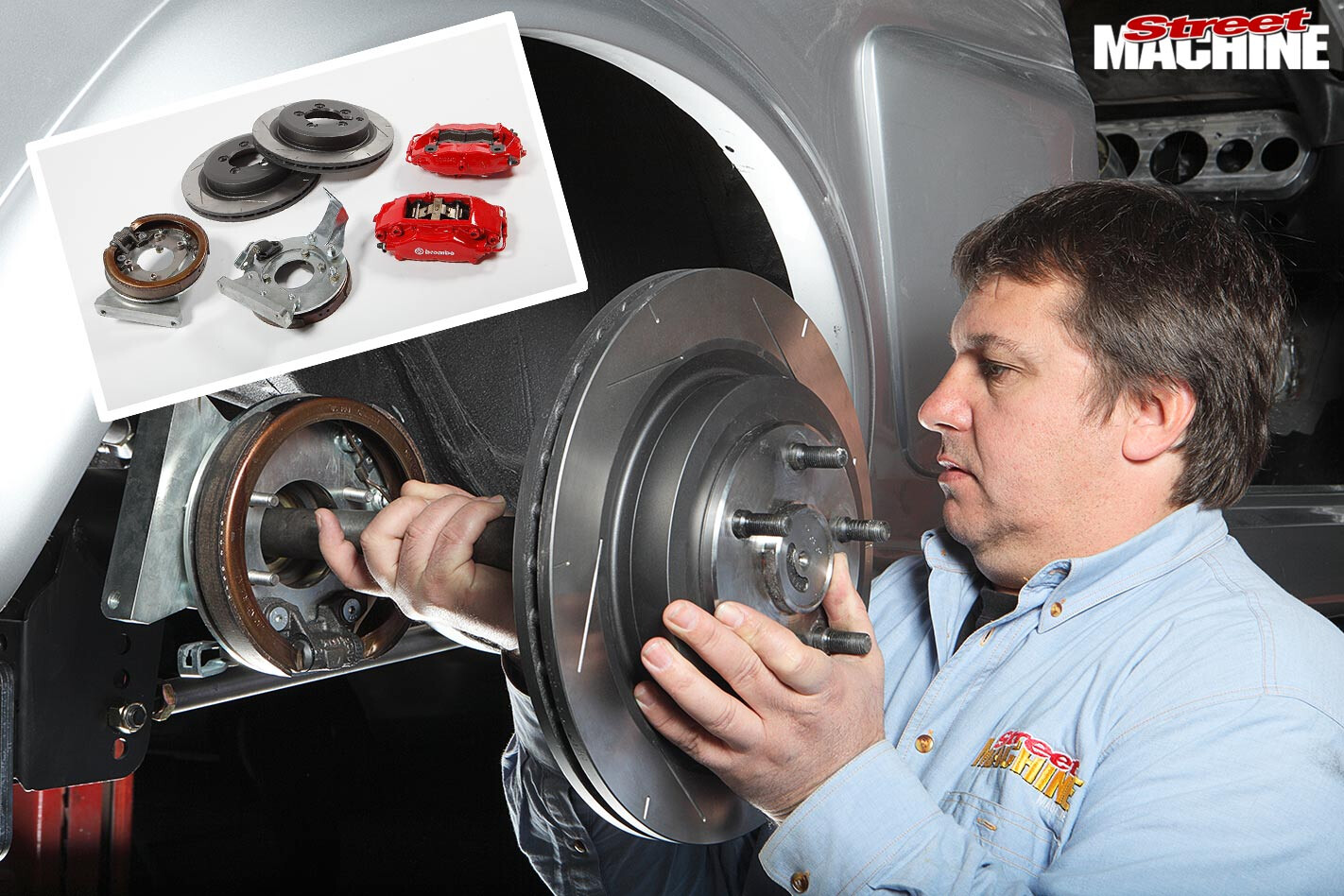 13. With the housing supported, the centre, axles and brakes were installed. While McDonalds does offer a disc brake set-up, this customer had already fitted RRS front struts complete with Brembo brake package so he went for one RRS’s bolt-on nine-inch disc brake conversions, with the optional Brembo calipers. For optimum strength, the nine-inch was equipped with tough 31-spline axles.
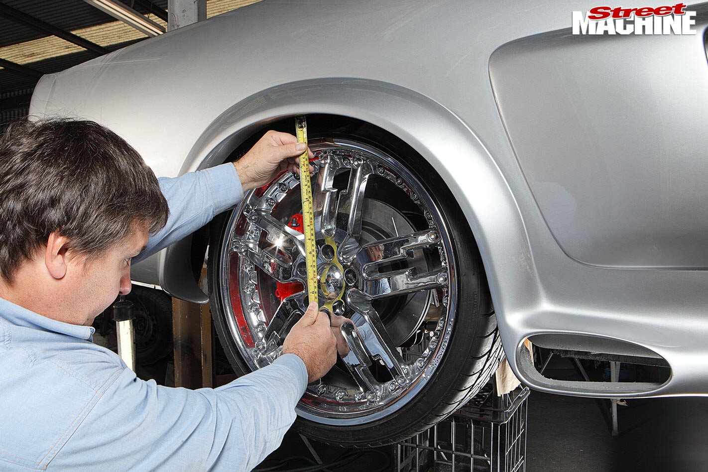 14. Detach the coil-overs (or remove the springs) and set the vehicle at the desired ride height. Now adjust the lower links (see Step 16) to centre the wheel in the arch. Due to 60s manufacturing tolerances, you may not be able to get the tyres sitting centrally on both sides simultaneously with both arms equal in length, which is critical. In this case you’ll have to sacrifice perfect looks for equal arm length.
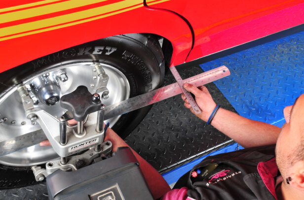
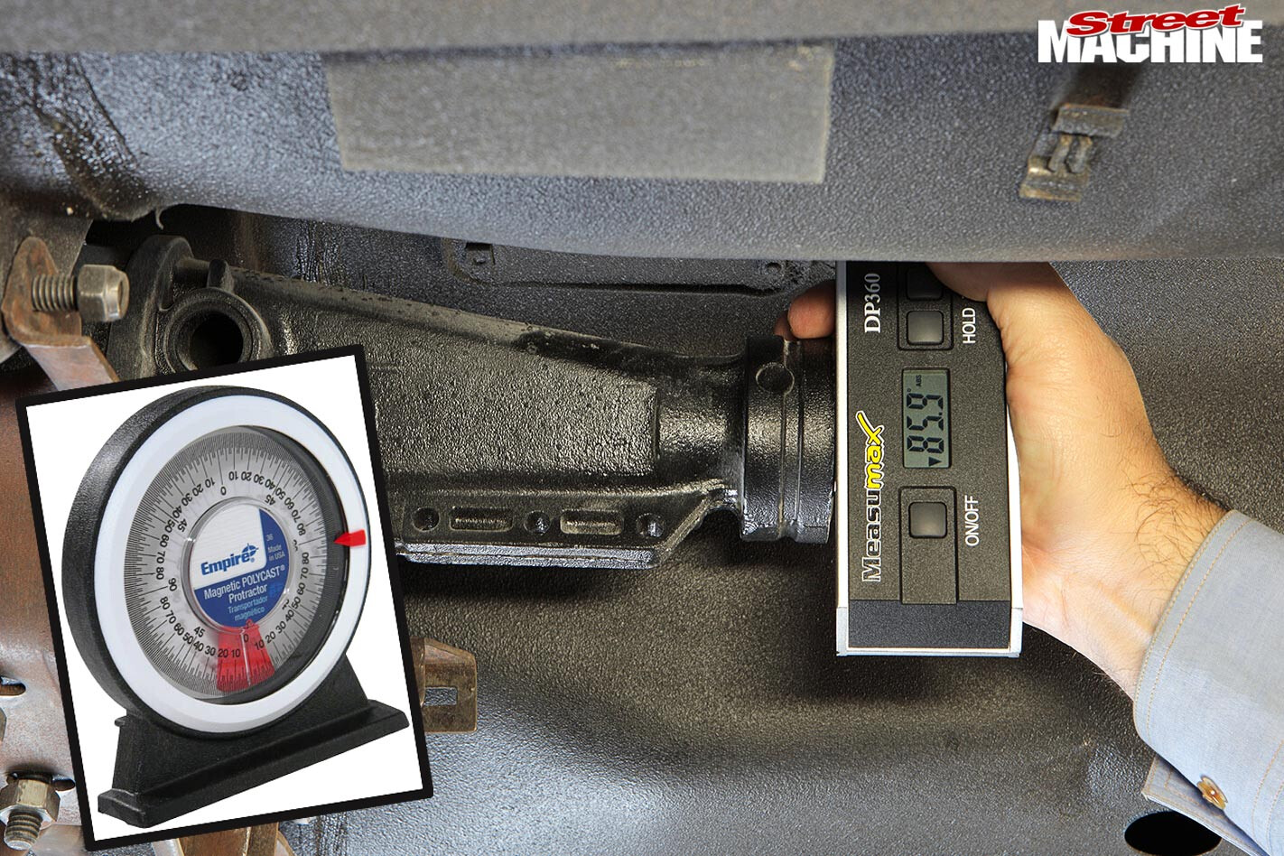 15. With the diff at ride height, set the static pinion angle — see In Theory (p120) for details. This requires measuring of the angle of the gearbox and pinion snout using an inexpensive gravity-style protractor (left) or an electronic one (above). In Steps 15 and 16, pinion angle is set to zero (their angles are equal but opposite as denoted by the arrow on the readout) to demonstrate their physical orientation.
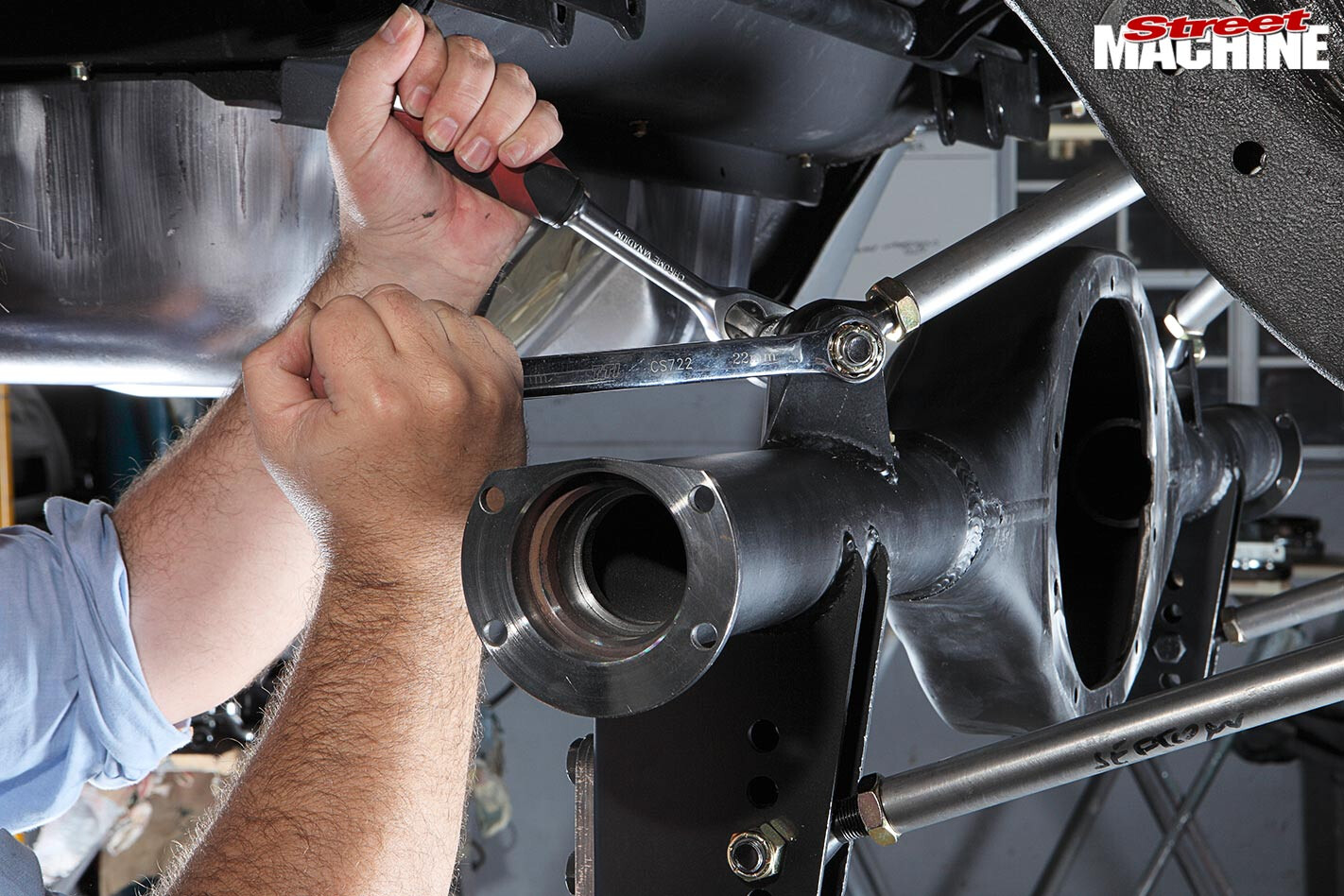
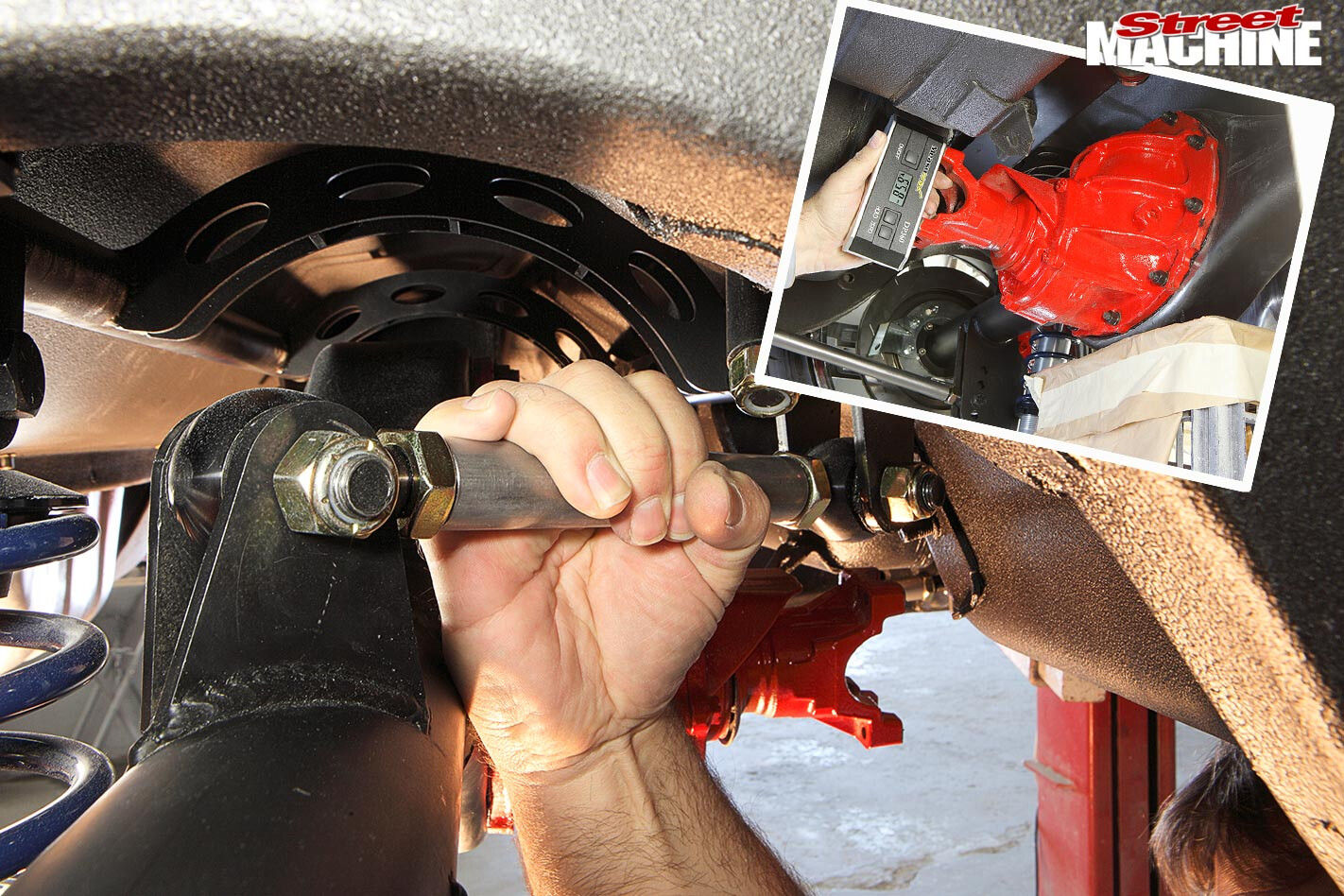 16. All of the links feature right-hand threads at one end, left-hand threads at the other — rotating the bar makes the link longer or shorter. Adjust the length of both top links (they must remain equal in length) until the desired static pinion angle is attained — we settled on around one-degree nose down. Recheck and reset wheel position if necessary, then tighten all the lock nuts on the adjustable bars.
WRAP UP
Dialling in final ride height, pinion angle and wheel position in the arches will probably take longer than the actual installation. Due to the sheer adjustability, it’s imperative that you have a four-wheel wheel alignment to ensure the differential is centred, so it doesn’t crab down the road, and straight, so that it’s not trying to steer the rear of the vehicle.
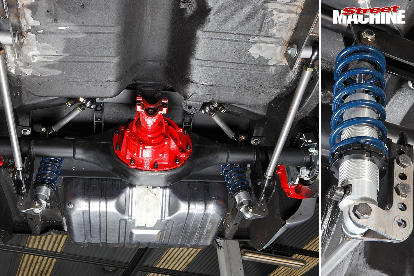 The design of the kit allows for plenty of suspension travel. In fact the differential here was able to move all the way up until the axle tubes contacted the chassis rail — the bump stops prevent this in service. This is great news for anybody looking to install very tall tyres and get their ride back down to a low-riding height.
While this kit pretty much dropped straight into place, always keep in mind that things tend to move around on any vehicle that has suffered many decades of wear and tear — on top of that, the original manufacturing tolerances were fairly loose back in the day. Therefore it’s not uncommon to experience differing fitment issues from one vehicle to another — some brackets may need some persuasion with a hammer, jack or G-clamp to ensure they’re fully seated.
For more info contact www.mcdonaldbrosracing.com.au

Comments